69
The corresponding power dispatching function is available only when the inverter
supports active power control, power factor control, and reactive power
regulation!
For details, refer to the inverter user manual or consult the local retailer.
8.2 Interface Description
The Logger1000 is equipped with digital control interfaces and analog control interfaces for
receiving digital instructions and analog instructions sent by the grid dispatching center.
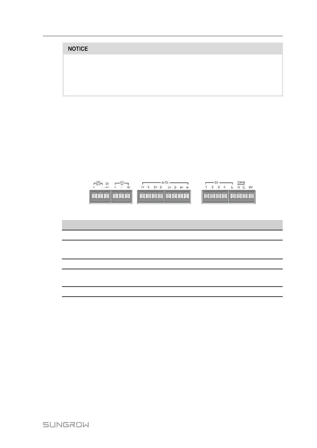
8.2.1 Digital Control Interface
The digital control interfaces are at the bottom of the Logger1000, and a sum of 5 digital in-
put ports are provided, as shown in the figure below.
table 8-1 Digital control interface signal definition
Signal
Definition
DI
Enabling switch for converting AI function to DI function
1+,1-,2+,2-
3+,3-,4+,4-
4 input dry contact channels
1,2,3,4,5
5 independent-input dry contact signal channel
DRM
Works together with the DI1 to DI4 to achieve the DRM
function
0V
Input dry contact signal ground
There are 4 ports at the bottom of the Logger1000 compatible with the AI/DI function. When
the DI function of the "AI/DI" port is enabled, use a power cable to connect the "24V OUT+"
port to "DI" port.
Wiring between the Logger1000 and the wireless receiver controller is as follows:
User Manual 8 Grid Dispatching Function

 Loading...

