38
However if an external residual current device (RCD) (type A is recommended) is mandatory,
the switch must be triggered at a residual current of 300 mA (recommended). RCD of other
specifications can also be used according to local standard.
In Australia, a RCD is not required according to the local standard AS3000-2018 when either
of the following installation methods is adopted if the PV array capacitance to ground is large
(such as a tin roof):
• Use heavy duty conduits (such as metal bushing) when run PV and AC cables through
Cavity walls.
• Route the PV and AC cables through pipes (PVC or metal tubing), lay the cables and in-
stall them.
Multiple Inverters in parallel Connection
If multiple inverters are connected in parallel to the grid, ensure that the total number of par-
allel inverters does not exceed 5. Otherwise, please contact SUNGROW for technical
scheme.
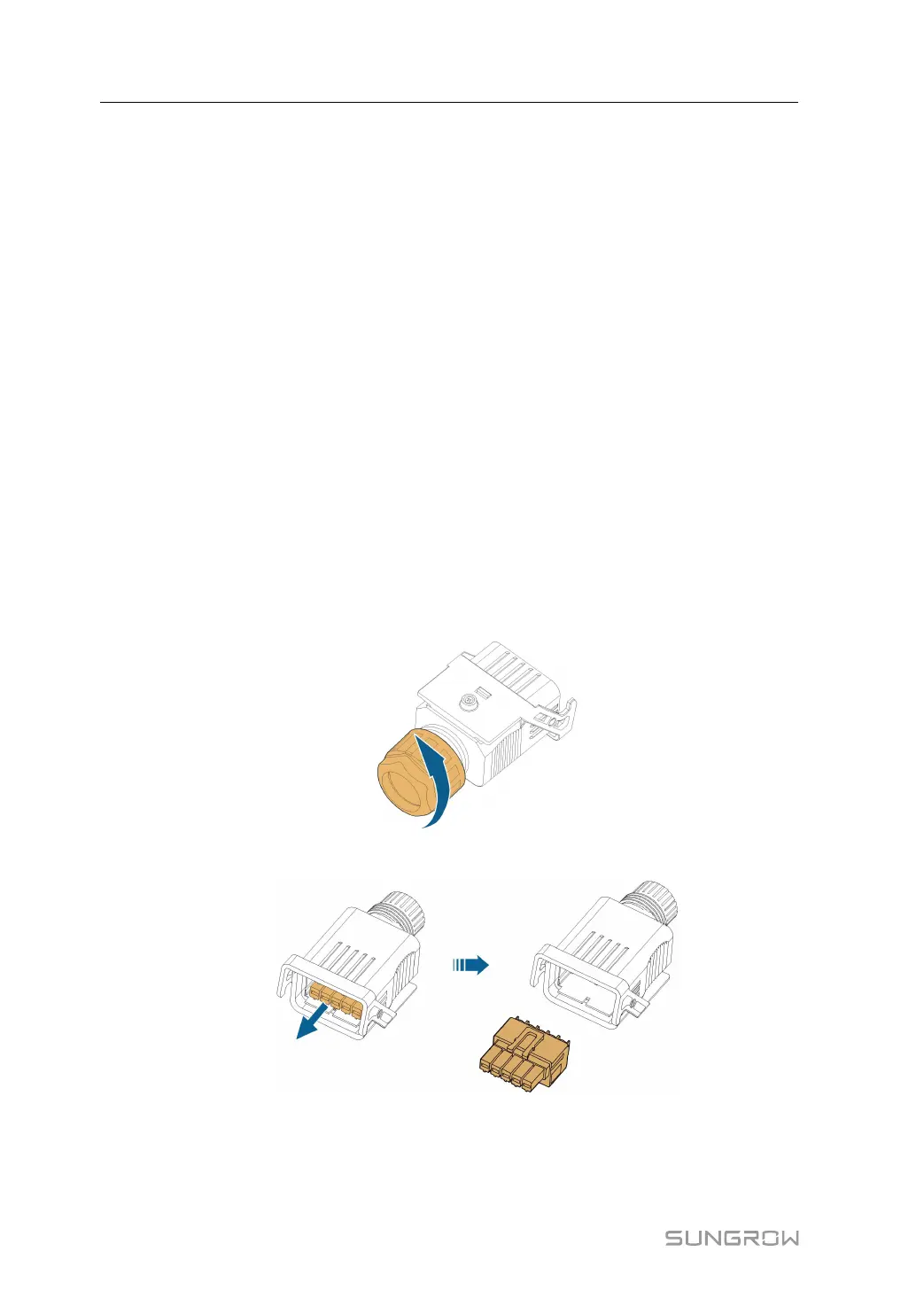
5.5.2 Assembling the AC Connector (< 15 kW)
The AC terminal block is on the bottom side of the inverter. AC connection is the three-
phase-four-wire grid + PE connection (L1, L2, L3, N, and PE).
step 1 Unscrew the swivel nut of the AC connector.
step 2 Take out the spring-loaded terminal from the housing.
step 3 Thread the AC cable of appropriate length through the swivel nut, the sealing ring and the
housing.
5 Electrical Connection User Manual
 Loading...