47
Note the following items when laying out cables on site:
• The axial tension on PV connectors must not exceed 80 N. Avoid axial cable
stress on the connector for a long time during field wiring.
• Radial stress or torque must not be generated on PV connectors. It may cause
the connector waterproof failure and reduce connector reliability.
• Leave at least 50 mm of slack to avoid the external force generated by the cable
bending affecting the waterproof performance.
• Refer to the specifications provided by the cable manufacturer for the minimum
cable bending radius. If the required bending radius is less than 50 mm, reserve
a bending radius of 50 mm. If the required bending radius is greater than 50 mm,
reserve the required minimum bending radius during wiring.
5.6.1 PV Input Configuration
• The inverters SG3.0RT/SG4.0RT/SG5.0RT/SG6.0RT/SG5.0RT-P2/SG6.0RT-P2 have
two PV inputs, SG7.0RT/SG8.0RT/SG10RT/SG12RT/SG7.0RT-P2/SG8.0RT-P2/
SG10RT-P2/SG12RT-P2 have three PV inputs and SG15RT/SG17RT/SG20RT/
SG15RT-P2/SG17RT-P2/SG20RT-P2 have four PV inputs.
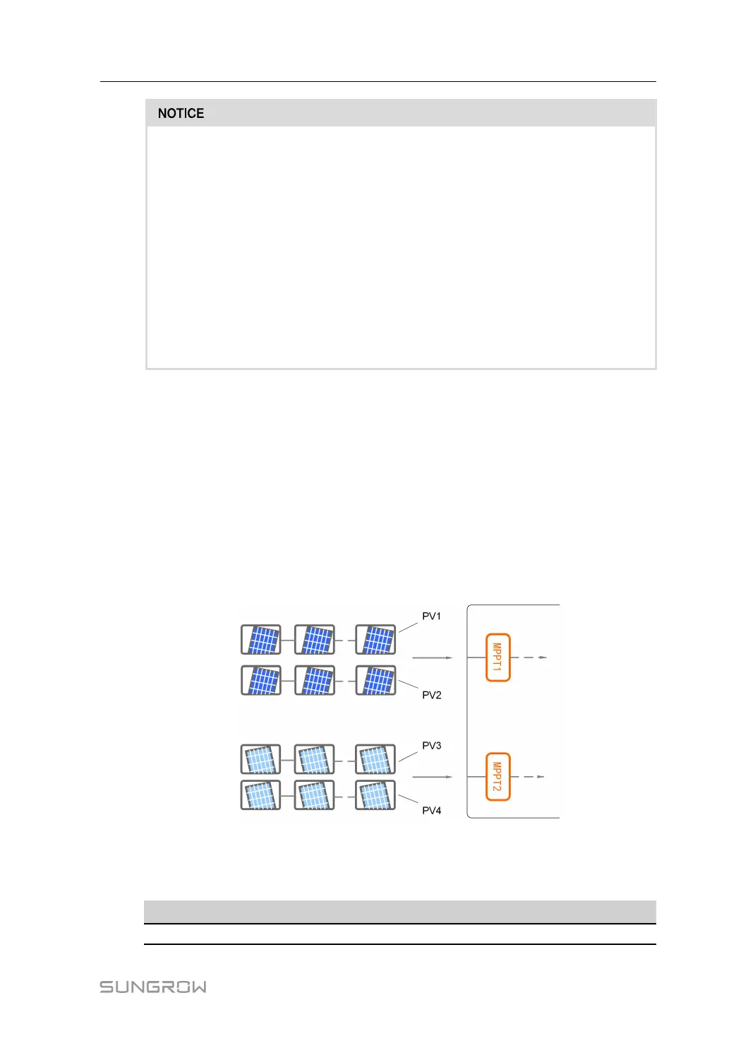
• The inverters have two MPP trackers. Each DC input area can operate independently.
• The PV strings to the same DC input area should have the same type, the same number
of PV panels, identical tilt and identical orientation for maximum power.
• The PV strings to two DC input areas may differ from each other, including PV module
type, number of PV modules in each string, angle of tilt, and installation orientation.
figure 5-3 PV Input Configuration (SG20RT for example)
Prior to connecting the inverter to PV inputs, the specifications in the following table should
be met:
Inverter Model
Open-circuit Voltage Limit Max. current for input connector
All models 1100 V 30 A
User Manual 5 Electrical Connection
 Loading...