67
table 5-4 Method of Asserting DRM
Mode Asserted by Shorting Terminals on
Inverter
Switch Operation on External
DRED
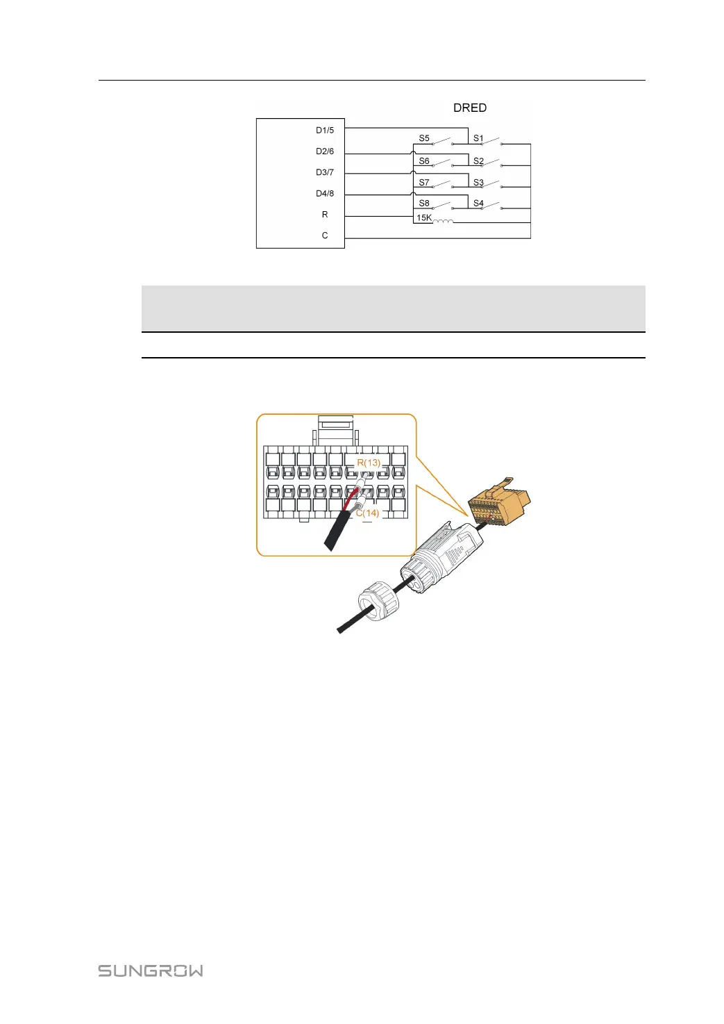
DRM0 R & C Close S1 and S5
Refer to section "5.9.1 Assembling the COM Connector" for detailed assembling procedure.
Plug the wires to R and C terminals according the labels on the bottom of the inverter.
Refer to section "5.10.3 Installing the COM Connector" to install the connector.
5.13 DI Connection
The grid company uses a Ripple Control Receiver to convert the grid dispatching signal and
send it as a dry contact signal.
The following figure shows the wiring between the inverter and the ripple control receiver.
User Manual 5 Electrical Connection
 Loading...