4-2 ELECTRICAL
M
+
–
WW
W W WWW W
Main relay
To ECM
To Fuel injector
To Ign. coil
To Fuel pump
Other
Sub Fuse 30A Main Fuse 60A
To ECM
From Ign. switch
To Ign. switch
To PTT switch
BATTERY
To Starter relay
Starter motor
Rectifier &
Regulator
Alternator (Magneto)
Battery charge coil
Gr
P/B
Gr
W
W
W
W
W
B
W
W
W
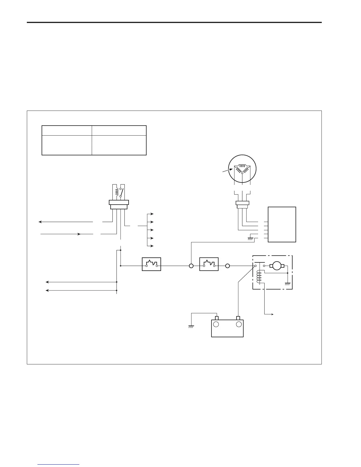
BATTERY CHARGING SYSTEM
OUTLINE
The battery charging system circuit is illustrated below.
It is composed of the BATTERY CHARGE COIL, RECTIFIER
& REGULATOR and BATTERY.
The three phase AC current generated from battery charge coil
is converted by the rectifier & regulator into regulated DC cur-
rent which is used to charge the battery.
OUTPUT
REGULATED
VOLTAGE
480 W (12V 40A)
14.2 – 15.2 V

 Loading...


