GENERAL INFORMATION 1-15
9.8 (0.39)
mm (in)
STD
5.5 (0.22)
mm (in)
Limit
STD
Limit
mm (in)
mm (in)
22.0 (0.87)
21.0 (0.83)
PTT MOTOR
Brush length
Commutator outside
diameter
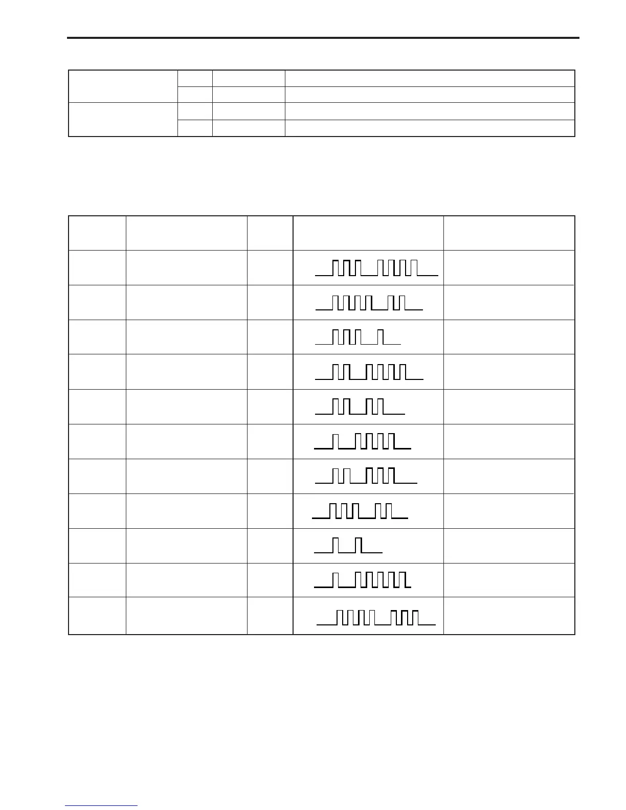
SELF-DIAGNOSTIC SYSTEM INDICATION
When the abnormality occurs in a signal from sensor, switch, etc., the “CHECK ENGINE” lamp on the moni-
tor-tachometer flashes (lights intermittently) according to the each code pattern with buzzer sounding.
PRIORITY
*
FAILED ITEM
CODE LAMP FLASHING PATTERN
FAIL-SAFE SYSTEM
ACTIVATING
1
MAP sensor 1 3 – 4
on
off
YES
2
CKP sensor 4 – 2
on
off
YES
3
IAC valve / By-pass air
screw adjustment
3 – 1
on
off
NO
4
CMP sensor 2 – 4
on
off
YES
5
CTP switch 2 – 2
on
off
NO
6
Cylinder temp. sensor 1 – 4
on
off
YES
7
IAT sensor 2 – 3
on
off
YES
8
MAP sensor 2
(Pressure detect passage)
3 – 2
on
off
NO
9
1 – 1
on
off
NO
Rectifier & regulator
(Over-charging)
* If more than two items fail at once, the self-diagnostic indication appears according to priority order.
The indication repeats three times.
10
1 – 5
on
off
YES
Exhaust manifold temp.
sensor
NO
4 – 3
on
off
Fuel injector
11

 Loading...


