POWER TRIM AND TILT 8-17
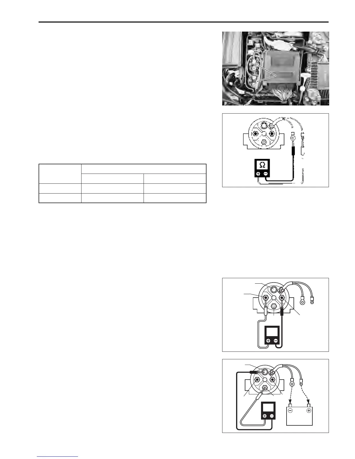
PTT MOTOR RELAY
Two methods can be used to test PTT motor relays.
Method 1.
Measure resistance between two lead wires of relay.
\ 09930-99320 : Digital tester
V Tester range :
Ω Ω
Ω Ω
Ω (Resistance)
Method 2.
1. Inspect relay operation using battery (12V) as follows:
\ 09930-99320 : Digital tester
T Tester range :
@@
@@
@ (Continuity)
(1) Without lead wires connected to battery, there should be
continuity between terminals 1, 2 and 3 but should be
no continuity between terminals 3 and 4.
(2) With Black lead wire connected to battery negative - ter
minal and Light blue (or Pink) lead wire connected to
battery positive + terminal, there should be continuity
between terminals 2, 3 and 4.
2. The relay is considered to be without defect if continuity test
results are as stated above.
PTT motor relay solenoid coil resistance : 3.0 – 4.5
ΩΩ
ΩΩ
Ω
Tester probe connection
Red
++
++
+ Black
--
--
-
UP relay Light Blue Black
DOWN relay Pink Black
B
Lbl(P)
Lbl(P)
CONT
1
2
3
4
CONT
Lbl(P)
B
12V BAT.
1
2
3
4
B
PTT motor relayPTT motor relay