FI SYSTEM DIAGNOSIS 12-26
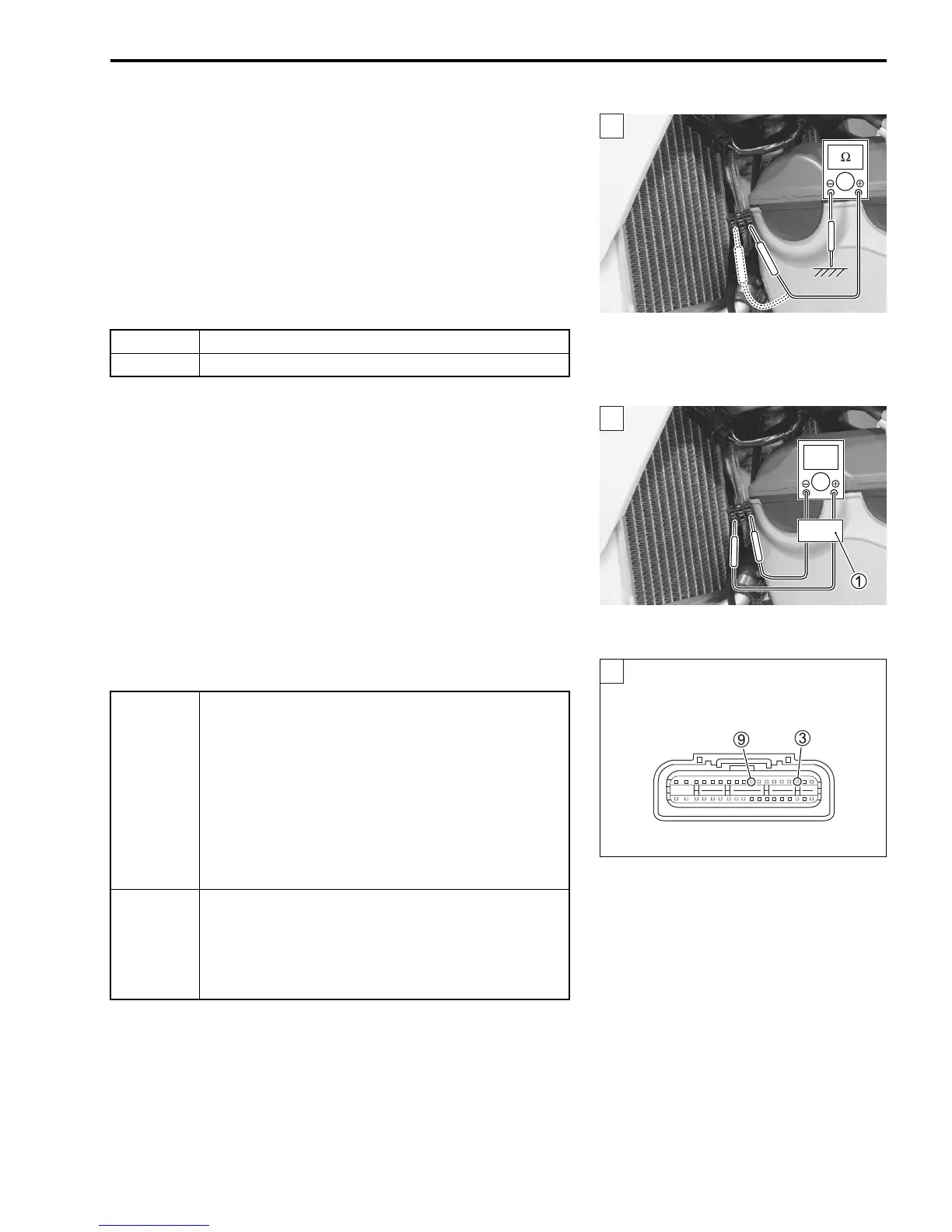
4) If OK, then check the continuity between each terminal and
ground.
# CKP sensor resistance: ∞ Ω (Infinity)
(Green – Ground)
(Red – Ground)
! 09900-25008: Multi-circuit tester set
$ Tester knob indication: Resistance (Ω)
Are the resistance and continuity OK?
Step 2
1) Measure the CKP sensor peak voltage by depressing the kick
starter lever several times forcefully.
2) Repeat the above test procedure a few times and measure
the highest peak voltage.
# CKP sensor peak voltage: 2.8 V and more
(
+ Green –
- Red)
1 Peak volt adaptor
! 09900-25008: Multi-circuit tester set
% Tester knob indication: Voltage (&)
.
Is the voltage OK?
YES Go to step 2.
NO Replace the CKP sensor with a new one.
YES
• G/W or BI wire open or shorted to ground.
• Loose or poor contacts on the CKP sensor cou-
pler or ECM coupler (terminal
3 or
9).
• If wire and connection are OK, intermittent trou-
ble or faulty ECM.
• Recheck each terminal and wire harness for
open circuit and poor connection.
• Replace the ECM with a known good one, and
inspect it again.
NO
• Inspect that metal particles or foreign material
stuck on the CKP sensor and rotor tip.
• If there are no metal particles and foreign mate-
rial, then replace the CKP sensor with a new
one.
ECM coupler (Harness side)
2

 Loading...


