FI SYSTEM DIAGNOSIS 12-34
“21” IAT SENSOR CIRCUIT MALFUNCTION
INSPECTION
Step 1
1) Stop the engine.
2) Remove the seat and fuel tank rubber band. ("5-2)
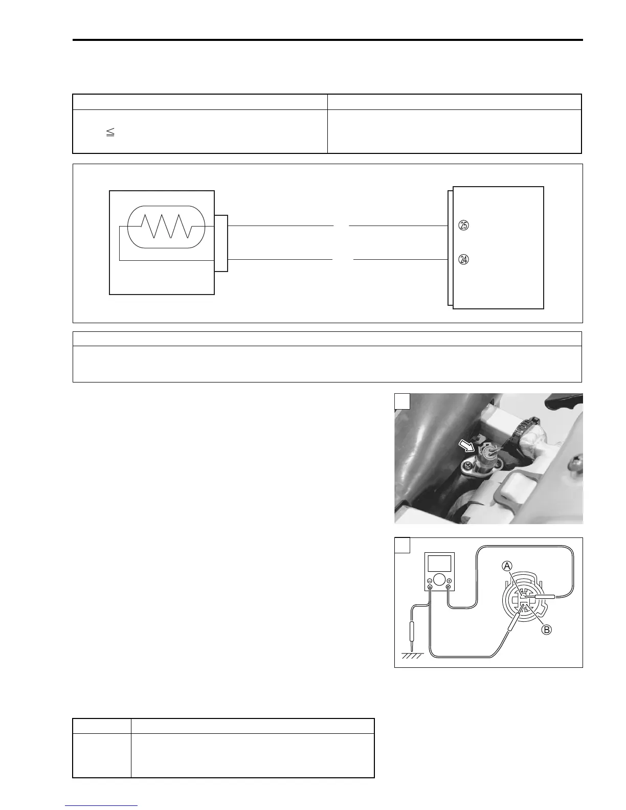
3) Check the IAT sensor coupler for loose or poor contacts.
If OK, then measure the IAT sensor voltage at the wire side
coupler.
4) Disconnect the IAT sensor coupler.
5) Connect a 12 volts battery using the battery lead wire to ser-
vice coupler. ("12-22)
6) Measure the voltage between Dg wire terminal
A and
ground.
7) If OK, then measure the voltage between Dg wire terminal
A
and B/Br wire terminal
B.
# IAT sensor input voltage: 4.5 – 5.5 V
(
+ Dg –
- Ground)
(
+ Dg –
- B/Br)
! 09900-25008: Multi-circuit tester set
36890-28H00: Battery lead wire (option)
% Tester knob indication: Voltage (&)
Is the voltage OK?
DETECTED CONDITION POSSIBLE CAUSE
Output voltage is not within the following range.
0.2 V Sensor voltage < 4.8 V
• IAT sensor circuit open or short.
• IAT sensor malfunction.
• ECM malfunction.
CAUTION
When using the multi-circuit tester, do not strongly touch the terminal of the ECM coupler with
a needle pointed tester probe to prevent the terminal damage or terminal bend.
ECM
B/Br
E2
IAT
Dg
IAT sensor
YES Go to Step 2.
NO
• Loose or poor contacts on the ECM coupler
(terminal
N or
O).
• Open or short circuit in the Dg wire or B/Br wire.

 Loading...


