12-25 FI SYSTEM DIAGNOSIS
“12” CKP SENSOR CIRCUIT MALFUNCTION
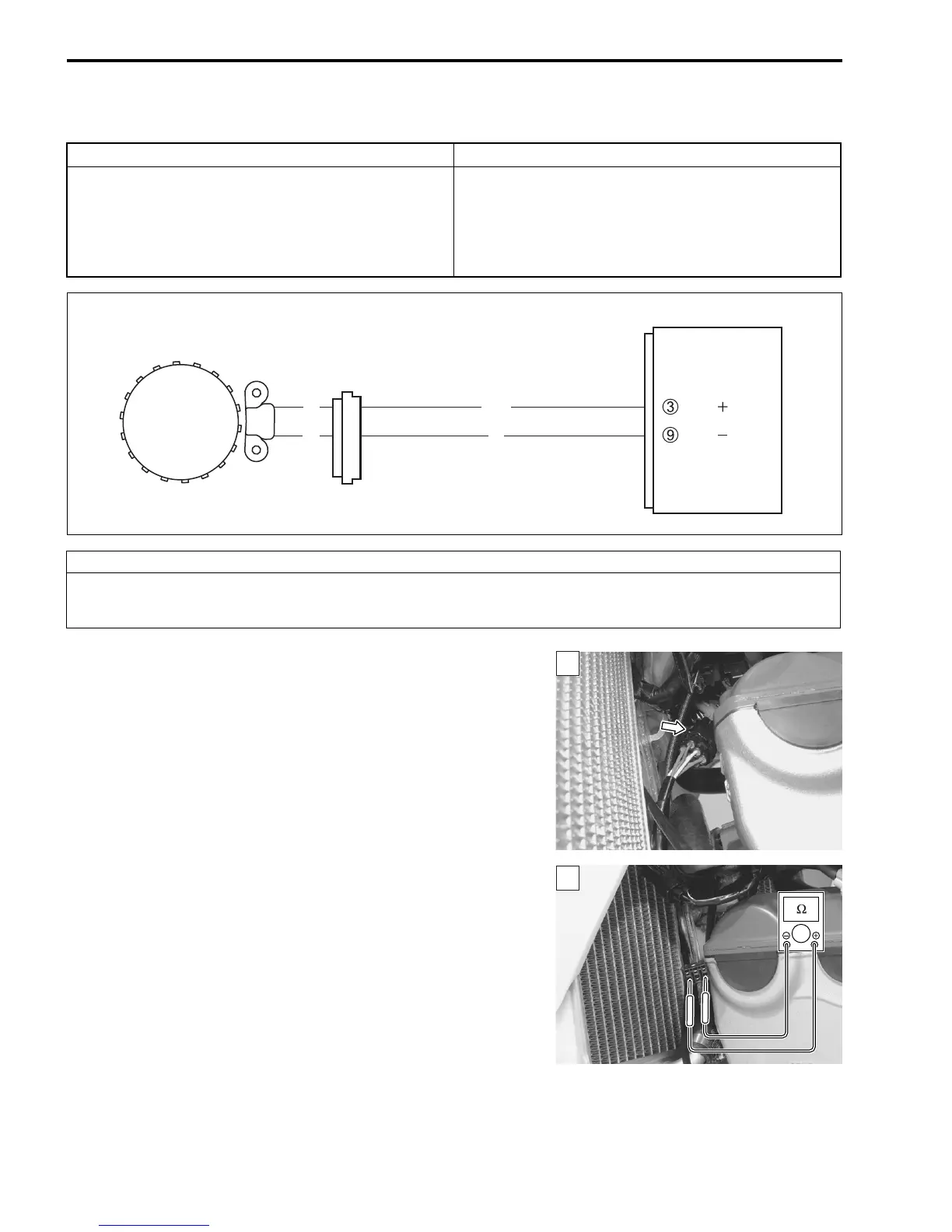
INSPECTION
Step 1
1) Stop the engine.
2) Check the CKP sensor coupler for loose or poor contacts.
If OK, then measure the CKP sensor resistance.
3) Disconnect the CKP sensor coupler and measure the resis-
tance.
# CKP sensor resistance: 80 – 120 Ω
(Green – Red)
DETECTED CONDITION POSSIBLE CAUSE
The signal does not reach ECM for 1 sec. or more,
after receiving the IAP sensor input signal.
• Metal particles or foreign material being stuck on
the CKP sensor and rotor tip.
• CKP sensor circuit open or short.
• CKP sensor malfunction.
• ECM malfunction.
ECM
CKP sensor
CKP
CKP
G/W
R
G
BI
CAUTION
When using the multi-circuit tester, do not strongly touch the terminal of the ECM coupler with
a needle pointed tester probe to prevent the terminal damage or terminal bend.

 Loading...


