12-37 FI SYSTEM DIAGNOSIS
Step 2
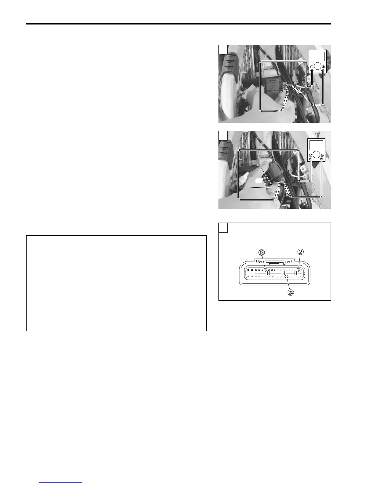
1) Connect the TO sensor coupler.
2) Insert the needle pointed probes to the lead wire coupler.
3) Connect a 12 volts battery using the battery lead wire to ser-
vice coupler. ("12-22)
4) Measure the voltage at the wire side coupler between Br/W
and B/Br wires.
# TO sensor voltage (Normal): 0.4 – 1.4 V
(
+ Br/W –
- B/Br)
Also, measure the voltage when leaning the motorcycle.
5) Measure the voltage when it is leaned 65° and more, left and
right, from the horizontal level.
# TO sensor voltage (Leaning): 3.7 – 4.4 V
(
+ Br/W –
- B/Br)
! 09900-25008: Multi-circuit tester set
09900-25009: Needle pointed probe set
36890-28H00: Battery lead wire (option)
% Tester knob indication: Voltage (&)
Is the voltage OK?
“24” IGNITION SYSTEM MALFUNCTION
* Refer to the IGNITION SYSTEM for details. ("15-11)
YES
• Br/W, R/Bl or B/Br wire open or shorted to
ground, or poor
2,
C or
N connection.
• If wire and connection are OK, intermittent trou-
ble or faulty ECM.
• Recheck each terminal and wire harness for
open circuit and poor connection.
• Replace the ECM with a known good one, and
inspect it again.
NO
• Loose or poor contacts on the ECM coupler.
• Open or short circuit.
• Replace the TO sensor with a new one.
ECM coupler (Harness side)
2

 Loading...


