11-7 LUBRICATION SYSTEM
OIL PUMP No.1 AND No.2 INSTALLATION
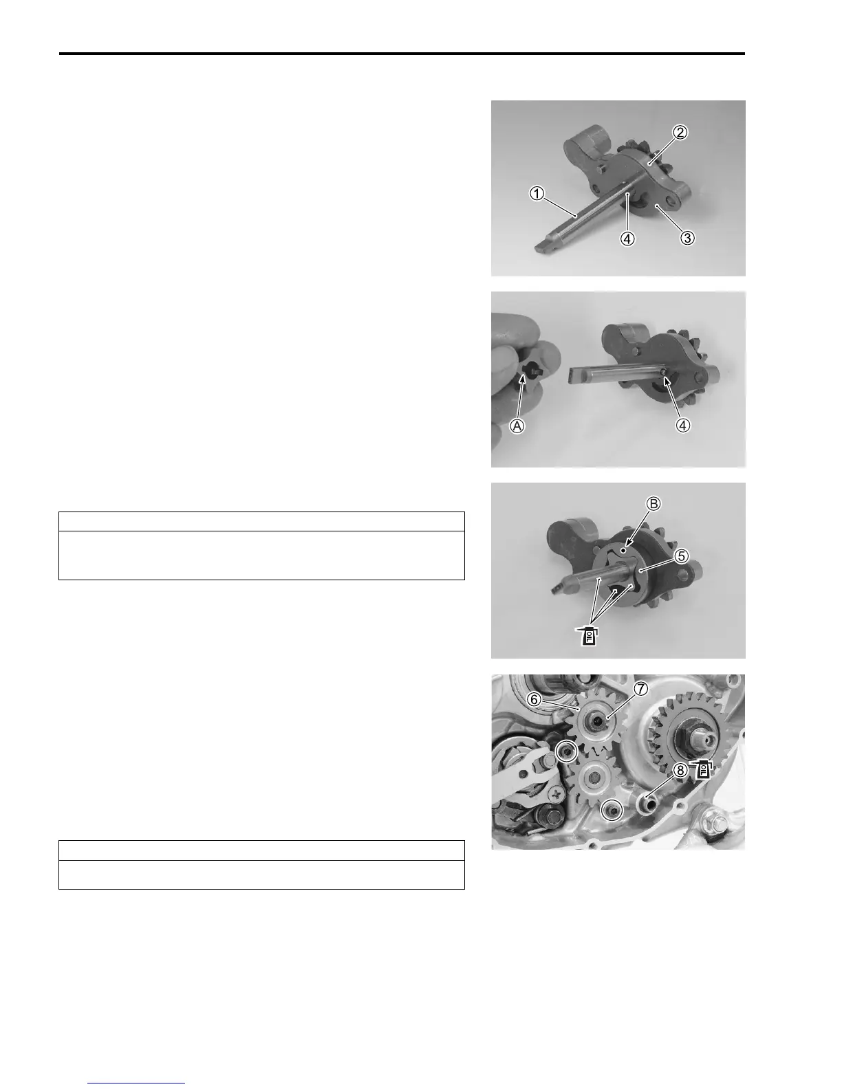
OIL PUMP No.1
Install the oil pump No.1 in the reverse order of removal. Pay
attention to the following points:
• Install the oil pump No.1 cover
2, oil pump No.1 plate
3 and
pin
4 onto the oil pump driven gear shaft
1.
• Fit the slot
A of the inner rotor onto the pin
4.
• Install the outer rotor
5.
• Apply engine oil to the oil pump driven gear shaft, outer rotor
and inner rotor.
• Install the oil pump No.1 and tighten the oil pump No.1 bolts to
the specified torque.
% Oil pump No.1 bolt: 5.5 N·m (0.55 kgf-m, 4.0 lb-ft)
• Install the oil pump idle gear
6, washer and snap ring
7.
" 09900-06107: Snap ring pliers
• Apply engine oil to the O-ring
8.
• Install the dowel pin and O-ring
8.
• Install the clutch component parts. (!7-9, -10)
• Install the right crankcase cover and kick starter lever.
(!8-6, -7)
• Install the brake pedal. (!17-18)
CAUTION
Face the punch mark
B on outer rotor
5 to the crank-
case.
CAUTION
Replace the snap ring
7 and O-ring
8 with new ones.

 Loading...


