12-39 FI SYSTEM DIAGNOSIS
4) Insert the needle pointed probes to the lead wire coupler.
5) Connect a 12 volts battery using the battery lead wire to ser-
vice coupler. ("12-22)
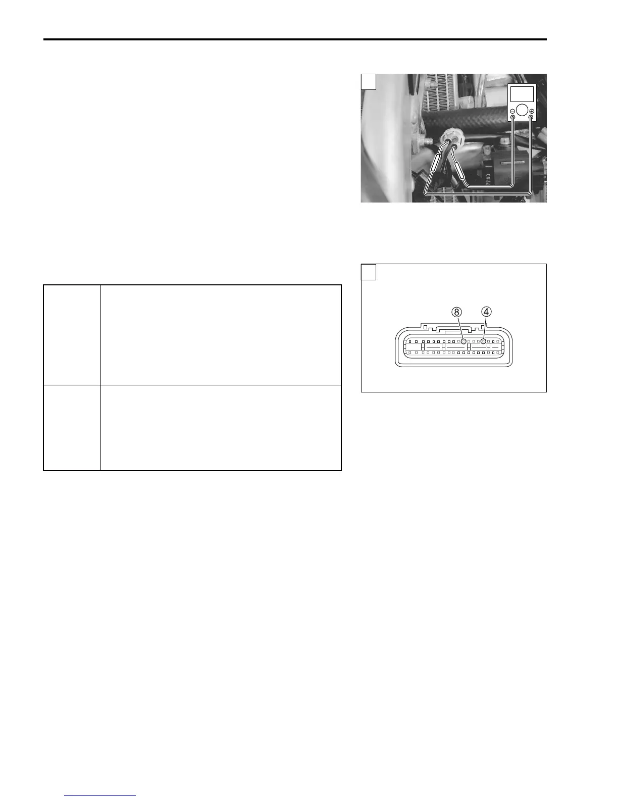
6) Measure the voltage at the wire side coupler between Pink
wire and B/W wire, when shifting the gearshift lever from 1st
to Top.
# GP switch voltage: 0.6 V and more
(
+ Pink –
- B/W)
! 09900-25008: Multi-circuit tester set
09900-25009: Needle pointed probe set
36890-28H00: Battery lead wire (option)
% Tester knob indication: Voltage (&)
Is the voltage OK?
YES
• Pink wire open or shorted to ground.
• If wire and connection are OK, intermittent trou-
ble or faulty ECM.
• Recheck each terminal and wire harness for
open circuit and poor connection.
• Replace the ECM with a known good one, and
inspect it again.
NO
• Pink or B/W wire open, or Pink wire shorted to
ground.
• Loose or poor contacts on the ECM coupler
(terminal
4 or
8).
• If wire and connection are OK, replace the GP
switch with a new one.
ECM coupler (Harness side)
1

 Loading...


