ELECTRICAL SYSTEM 15-16
CKP SENSOR AND CRANKSHAFT ROTATION
SIGNAL SENSOR RESISTANCE
• Disconnect the magneto lead wire coupler.
• Measure the resistance between the lead wires using the
multi-circuit tester. If the resistance is not within the specified
value, replace the stator with a new one.
# CKP sensor resistance: 80 – 120 Ω (Red – Green)
Crankshaft rotation signal sensor resistance:
0.1 – 0.8 Ω
(B/R – R/W
)
" 09900-25008: multi-circuit tester set
$ Tester knob indication: Resistance (Ω)
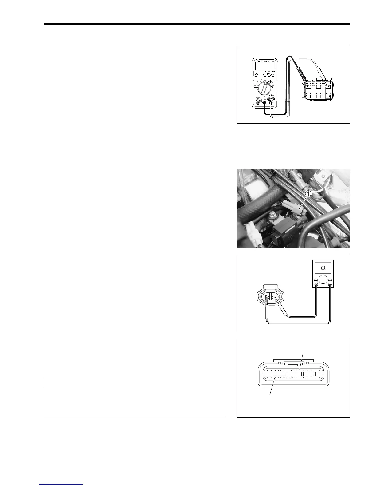
ENGINE STOP SWITCH
• Remove the seat, radiator covers and fuel tank. (!5-2)
• Disconnect the engine stop switch lead wire coupler
1.
• Measure the engine stop switch resistance between B/Y lead
wire and B/W lead wire.
# Engine stop switch resistance:
ON: Under 1
Ω
(B/Y – B/W
)
OFF:
∞
Ω
(
Infinity)
(B/Y – B/W
)
" 09900-25008: Multi-circuit tester set
09900-25009: Needle pointed probe set
& Tester knob indication: Resistance (Ω)
If the measurement is out of the specification, the cause may lie
in the engine stop switch.
If the measurement is within the specification, check the continu-
ity between the engine stop switch coupler and ECM coupler.
CAUTION
Normally, use the needle pointed probe to the back-
side of the lead wire coupler to prevent the terminal
bend and terminal alignment.
ECM coupler (Harness side)
B/W
B/Y

 Loading...


