AInstallation
D
Ref. DCD01/3078 - TD412_en_C
24/62
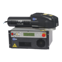
2. Marking area
Diagram showing marking areas for the 4 available lenses (F 100, F 160, F 254, F 330)
1 : Marking area (mm)
2 : Focal lens
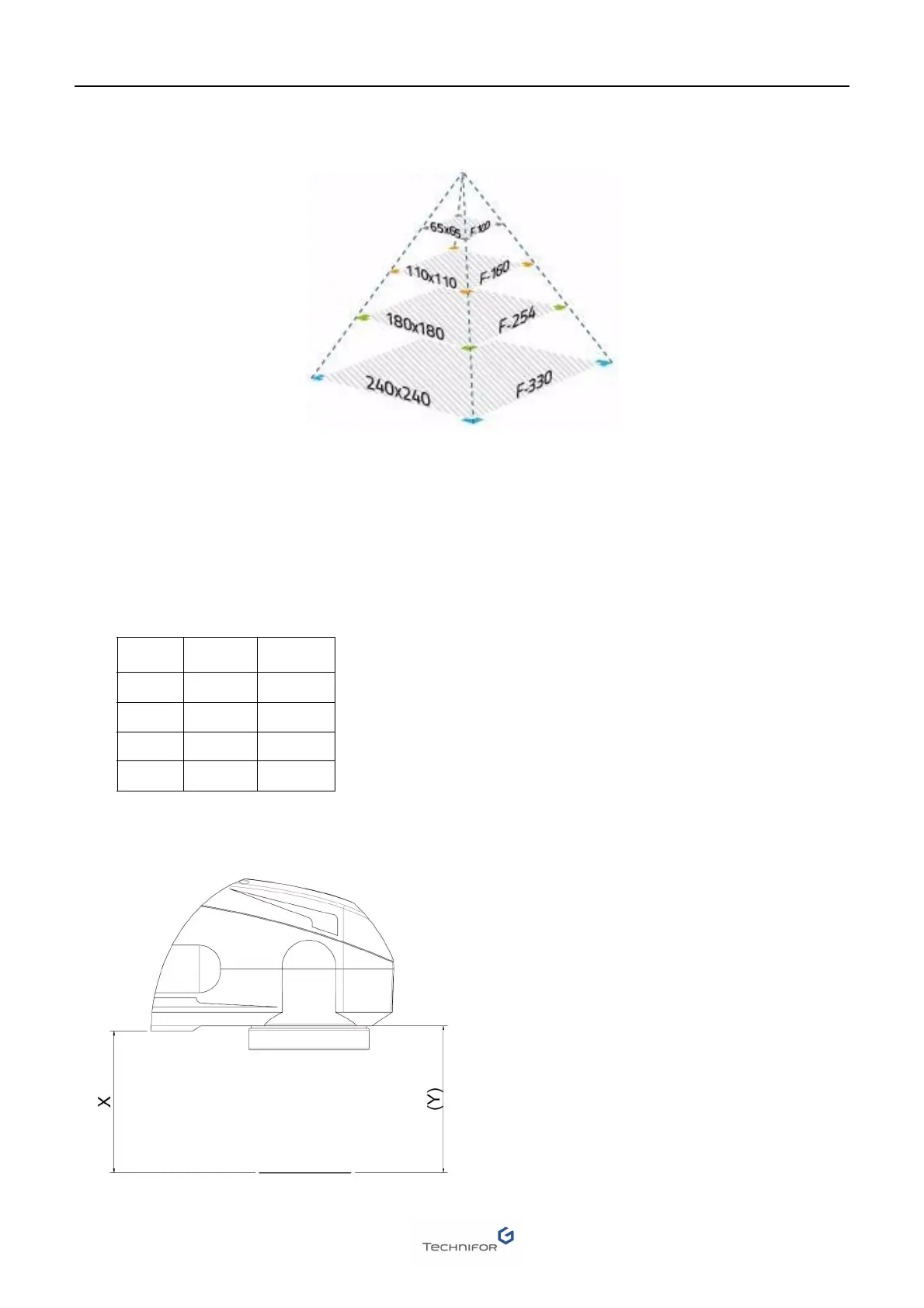
3. Height adjustment
For optimal marking quality, the part must be placed at the proper distance from the marking head. This is the
focal distance or working distance.
This distance varies depending on the focal lens used and the specific characteristics of the machine’s laser
beam (diameter and beam divergence).
These values are approximative.
Distances may vary approximately +/- 15 mm (0.591 in) depending on the laser’s and focal lens’ specific
characteristics.
1
2
LENS X (mm) Y (mm)
f 100 86 92
f 160 162 168
f 254 306 312
f 330 421 427
 Loading...