ACommunication
E
Ref. DCD01/3078 - TD412_en_C
41/62
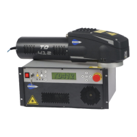
Minimum cabling required
An ancillary bridged connector DB37 is included with each laser for the purposes of shunting the external safety
device. This accessory allows the laser to be used without being integrated. Retain the connector to check the
operation of the marking machine independently of its integration.
The contact(s) 1-20 / 2-21 / 3-22 / 4-23 / 5-24 / 12-30 is/are bridged. This equates to shunting the emergency
stop, interlock, reset and key contact.
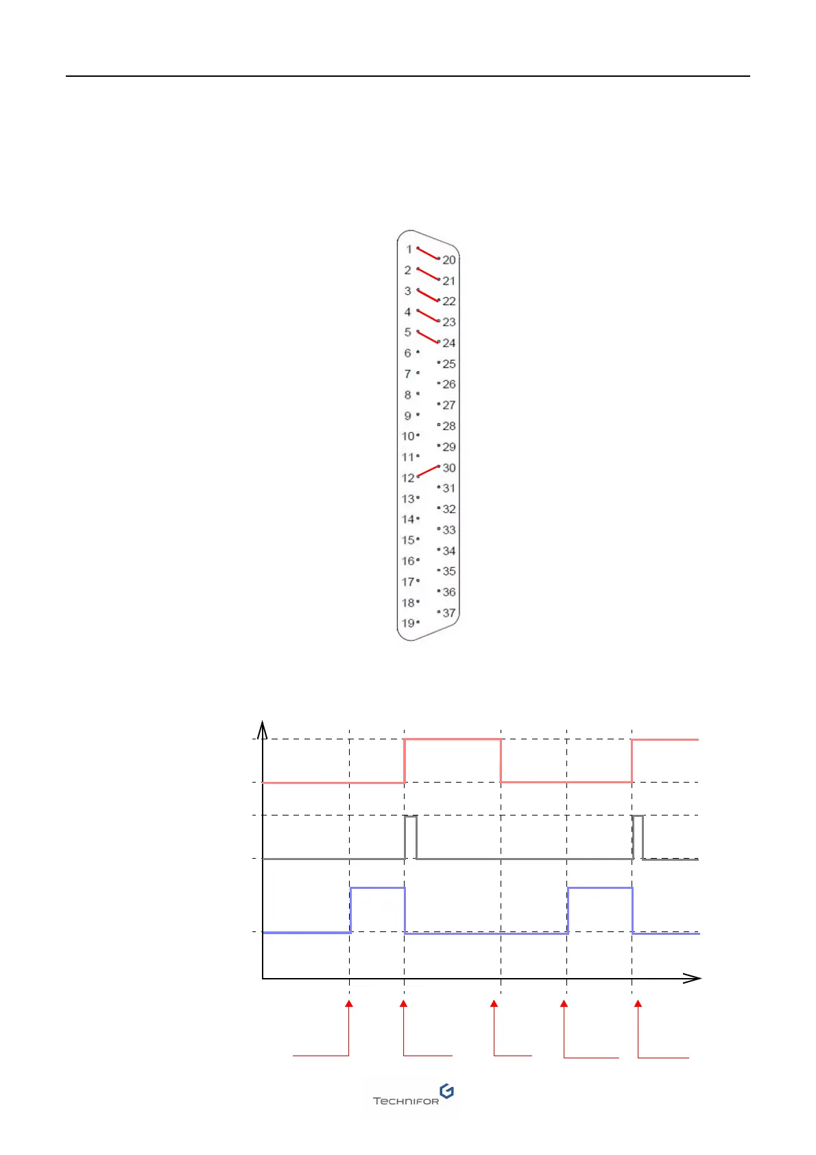
Timing diagrams of the communication signals
Emergency stop - B
Emergency stop - A
Interlock - B
Interlock - A
Stop marking
Start marking
Grounding - 0 V
Grounding - 0 V
Grounding - 0 V
Shutter command
Key contact
Information: "Laser" alarm
Information: Ready to marking
Information: Marking in progress
Information: Shutter’s condition
Information: Key state
Information: Emergency stop
Safety circuit reset
Emergency stop - A
Emergency stop - B
Interlock - A
Interlock - B
Stop marking
Start marking
Not available
+ 24 V DC
+ 24 V DC
+ 24 V DC
Shutter command
Key contact
Information: "Laser" alarm
Information: Ready to marking
Information: Marking in progress
Information: Shutter’s condition
Information: Key state
Information: Emergency stop
Safety circuit reset
Start marking
Marking in progress
Ready to marking
Start marking Start marking
End of
marking
cycle
Transmission
finished
Transmis-
sion
finished
 Loading...