ACommunication
E
Ref. DCD01/3078 - TD412_en_C
37/62
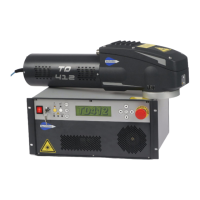
Description of Inputs
Example of wiring for an Input - dry contact
• Emergency stop (Input 1-20 / 2-21 - dry contact)
- Equivalent and remote function of the front of the CCU
- Use the 2 lines available.
- Contact between pins 1-20 and 2-21 closed: Emergency stop closed (normal operation)
- Contact between pins 1-20 and 2-21 open: Emergency stop activated
- Pins 1-20 and 2-21 at different statuses: The emergency stop is considered to be activated.
If the emergency stop opens:
- No laser emission is possible. The Key status Information contact 17-35 opens.
- The Emergency stop Information contact 18-36 closes.
- The shutter closes. The Shutter status Information contact 16-34 opens.
- The elements connected to the laser source are no longer powered.
Restart the machine using the start-up instructions:
- Close the dry contact between pins 1-20 and 2-21 and/or rotate to deactivate the Emergency Stop button on
the front of the CCU.
- Put the safety key in 0 position and/or open the contact between the 12 and 30 pins.
- Reset by closing the contact between pins 19-37 for 500 ms or press the "Safety circuit reset" button (CCU
front panel).
- Wait for the CCU to start up fully (green light).
- Put the safety key in 1 position. Close the dry contact between pins 12 and 30.
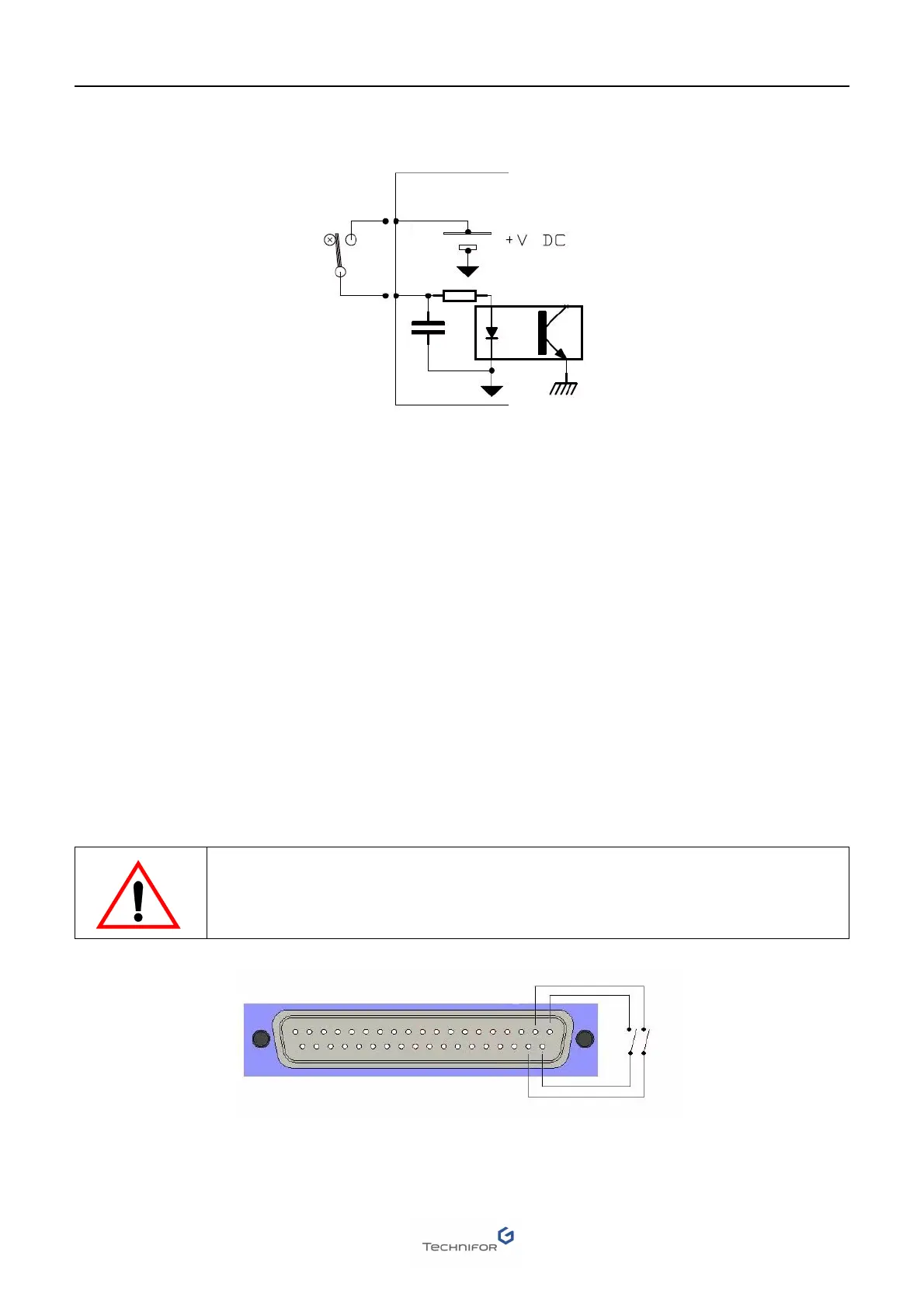
CAUTION: Do not create bridging between pins 1 and 2 and/or 20 and 21, to avoid
damaging the machine.
CCU side
12
20 21
 Loading...