CONTROLS, CONNECTORS AND
INDICATORS
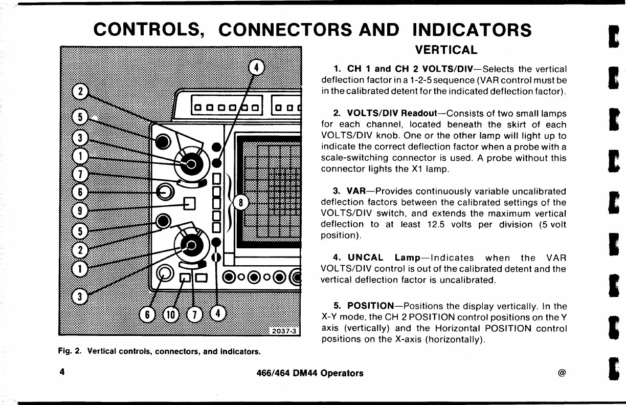
VERTICAL
1.
CH
1
and
CH
2
VOLTS/DIV-Selects
the vertical
deflection
factor
in a 1-2-5 sequence (VAR
control
must
be
in
the
calibrated detent
for
the indicated
deflection
factor).
2.
VOL
TS/DIV
Readout-Consists
of
two
small lamps
for
each channel, located beneath
the
skirt
of
each
VOL
TS/DIV
knob. One
or
the
other
lamp
will
light
up
to
indicate the
correct
deflection
factor
when a
probe
with
a
scale-switching
connector
is
used. A
probe
without
this
connector
lights
the
X1
lamp.
3.
VAR-Provides
continuously
variable
uncalibrated
deflection
factors between the calibrated settings
of
the
VOL
TS/DIV
switch, and extends the
maximum
vertical
deflection
to
at least 12.5 volts per
division
(5 volt
position).
4.
UNCAL
Lamp-Indicates
when
the
VAR
VOL
TS/DIV
control
is
out
of
the calibrated
detent
and the
vertical
deflection
factor
is uncalibrated.
5.
POSITION-Positions
the
display
vertically. In the
X-Y mode, the CH 2 POSITION
control
positions
on the Y
axis (vertically) and the
Horizontal
POSITION
control
positions on
the
X-axis (horizontally).
Fig.
2.
Vertical controls, connectors, and indicators.
4
466/464 DM44 Operators
@
I
I
I
E
I
I
I
I
I

 Loading...


