ALGEBRAIC
ADDITION
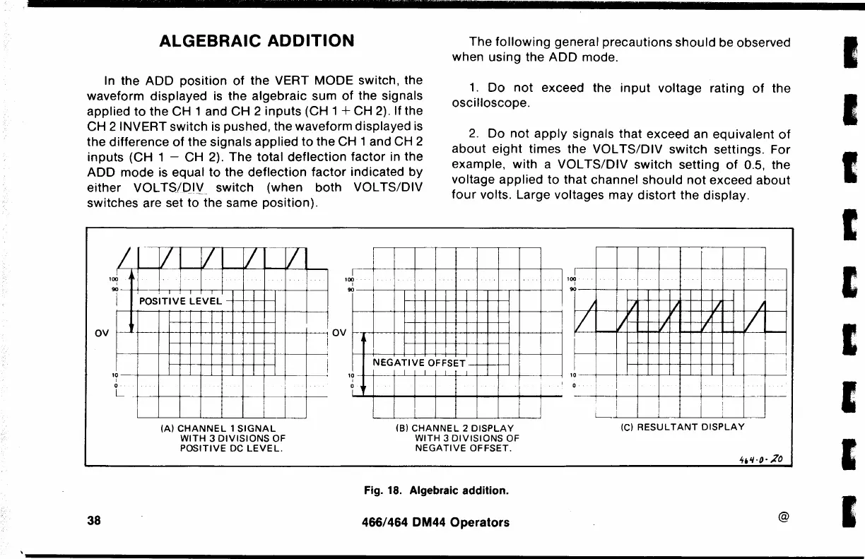
In the
ADD
position
of
the VERT MODE switch, the
waveform displayed
is
the algebraic sum
of
the signals
applied
to
the CH 1 and CH 2 inputs (CH 1 +
C~
2). If
th.e
CH 2 INVERT switch is pushed, the waveform displayed
1s
the difference
of
the signals applied
to
the CH 1 and CH 2
inputs (CH 1 - CH 2).
The
total
deflection
factor in the
ADD
mode
is equal
to
the
deflection
factor
indicated
by
either
VOL
TS/QIV switch (when both VOL TS/DIV
switches are set to-the same position).
ov
I
r
100
90
I
·~
t
I
v
I I I
POSITIVE
LEVEL
I
/'
l
I
I
I
100
90
OV
'
The
following
general precautions
should
be observed
when using the
ADD
mode.
1.
Do
not
exceed the
input
voltage rating
of
the
oscilloscope.
2.
Do
not
apply
signals
that
exceed an equivalent
of
about
eight
times the VOL
TS/DIV
switch
settings. For
example,
with
a VOL
TS/DIV
switch setting
of
0.5, the
voltage applied
to
that
channel
should
not
exceed
about
four
volts. Large voltages may
distort
the display.
I
I
I
100
90
I
I
)
/'
/
j
)
I/
j
.
.
I
I/
I
I
NEGATIVE
OFFSET -
'--1--->--
I
I
1?
0
L
38
i
(A)
CHANNEL
1
SIGNAL
WITH 3
DIVISIONS
OF
POSITIVE
DC
LEVEL.
1?
0
I
I
I
I
I
(B)
CHANNEL
2
DISPLAY
WITH 3
DIVISIONS
OF
NEGATIVE
OFFSET.
Fig.
18.
Algebraic addition.
466/464 DM44
Operators
10
I
I
0
---
I
I
L_i
(C)
RESULTANT
DISPLAY
@
I
I
I
I
I
I

 Loading...


