TM 11-6625-2735-14-1
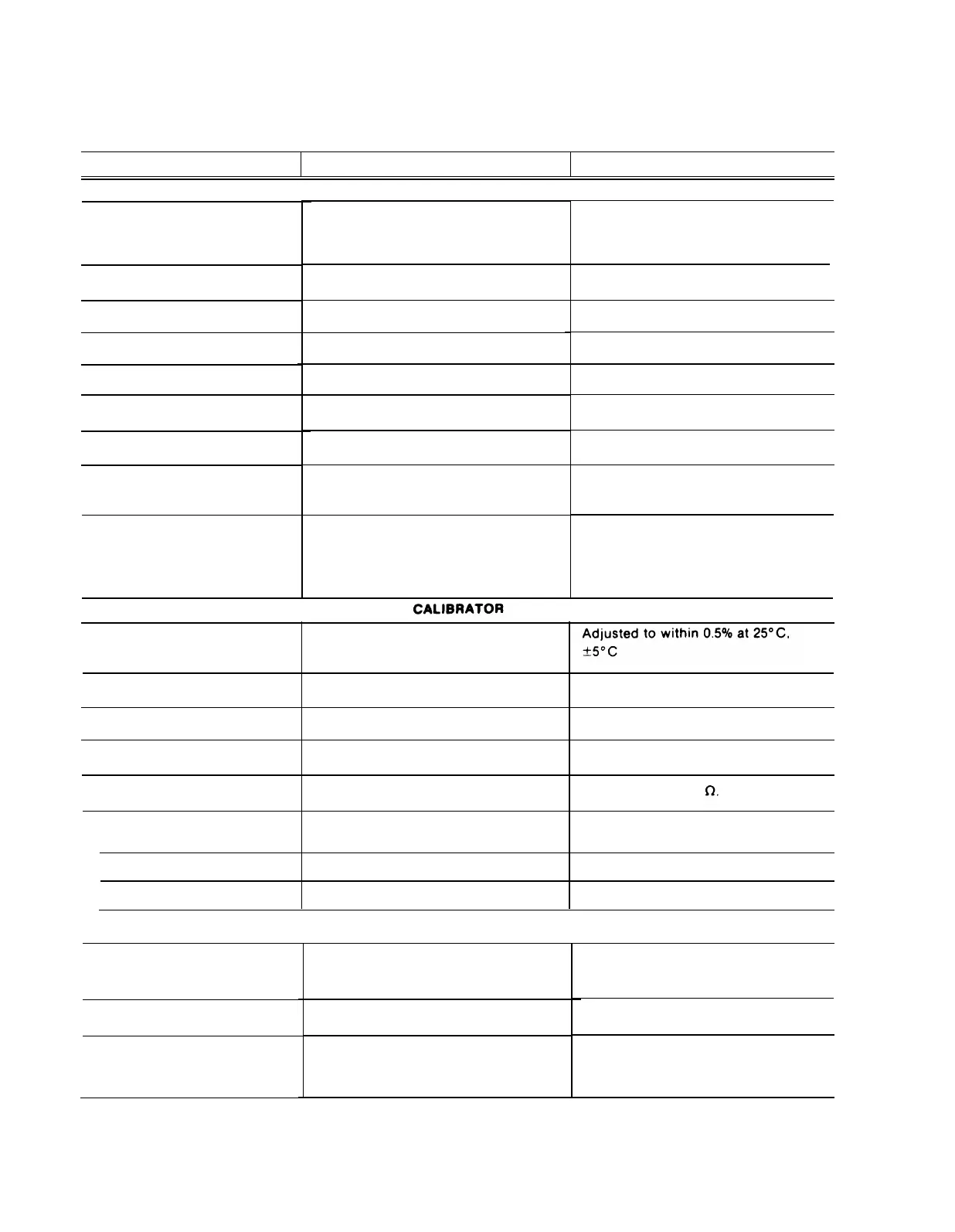
TABLE 1-1 (cont)
ELECTRICAL
Characteristics
Performance Requirements Supplemental Information
X-Y OPERATION
Same as vertical deflection system.
Extreme counterclockwise position of
TIME/DIV switch. CH 2 OR X-Y button
of VERT MODE switch must be pushed
Sensitivity
Deflection Accuracy
Variable Range
Same as vertical deflection system.
Same as vertical deflection system.
DC to 3 MHz.
X-Axis Bandwidth
Input Capacitance
Same as vertical deflection system.
Same as vertical deflection system.
Same as vertical deflection system.
Input Resistance
Maximum Input Voltage
Phase Difference Between X and
Y Axis Amplifiers
Within 1° from DC to 1 MHz.
Within 3° from 1 MHz to 2 MHz.
0.2 div or less compression or ex-
pansion of a 2 div signal at center
screen, positioned to horizontal
extremes of display area.
X Axis Low Frequency Linearity
Output Voltage
0°C to +40°C
300 mV within 1.0%.
300 mV within 1.5%.
–15°C to +55°C
Repetition Rate
Approximately 1 kHz. Within 25%.
Output Resistance
Approximately 9.4
Output Current
+20°C to +30°C
30 mA within 2%
–15°C to +55°C
30 mA within 2.5%
Z AXIS INPUT
Sensitivity
Positive-going signal from ground
decreases intensity.
100 V (DC plus peak AC).
100 V P-P AC at 1 kHz or less.
5 V P-P signal causes noticeable mod-
ulation at normal intensity.
Useable Frequency Range
DC to 50 MHz.
Maximum Input Voltage
1-8

 Loading...


