Removal and Installation Procedures
6-20 AFG3000 Series Arbitrary/Function Generators Service Manual
A72 CPU Board
You will need a torque-limiting Torx T-15 screwdriver, a torque wrench, a 16 mm
(5/8 inch) deep socket, 7 mm socket and needle-nose pliers.
Removal. To remove the CPU board, refer to Figure 6-16 and follow these steps:
1. Use the 7 mm socket torque wrench to remove the two hex screws and the two
washers attaching the GPIB connector to the rear sub-panel.
2. Remove the CH1 Add Input BNC connector:
a. Disconnect the peltola cable at J370 on the Generator board.
b. Use the 16 mm (5/8 inch) deep socket to remove the nut and the wave
washer from the BNC connector.
c. Push the CH1 Add Input BNC connector and the insulator bushing to
remove them from the rear sub-panel.
3. (AFG3022B, AFG3102, AFG3252 only)
Remove the EXT Modulation CH2 Input BNC connector:
a. Disconnect the Peltola cable at J852 on the CPU board.
b. Use the 16 mm (5/8 inch) deep socket to remove the nut and the spring
washer from the BNC connector.
c. Push the EXT Modulation CH2 Input BNC connector and the insulator
bushing to remove them from the rear sub-panel.
4. Remove the nuts and wave washers from the EXT Modulation CH1 Input, the
Ext Ref Input, and the Ext Ref Output connectors. These connectors are
mounted on the CPU board:
a. Use the 16 mm (5/8 inch) deep socket to remove the nuts and the spring
washers from these BNC connectors.
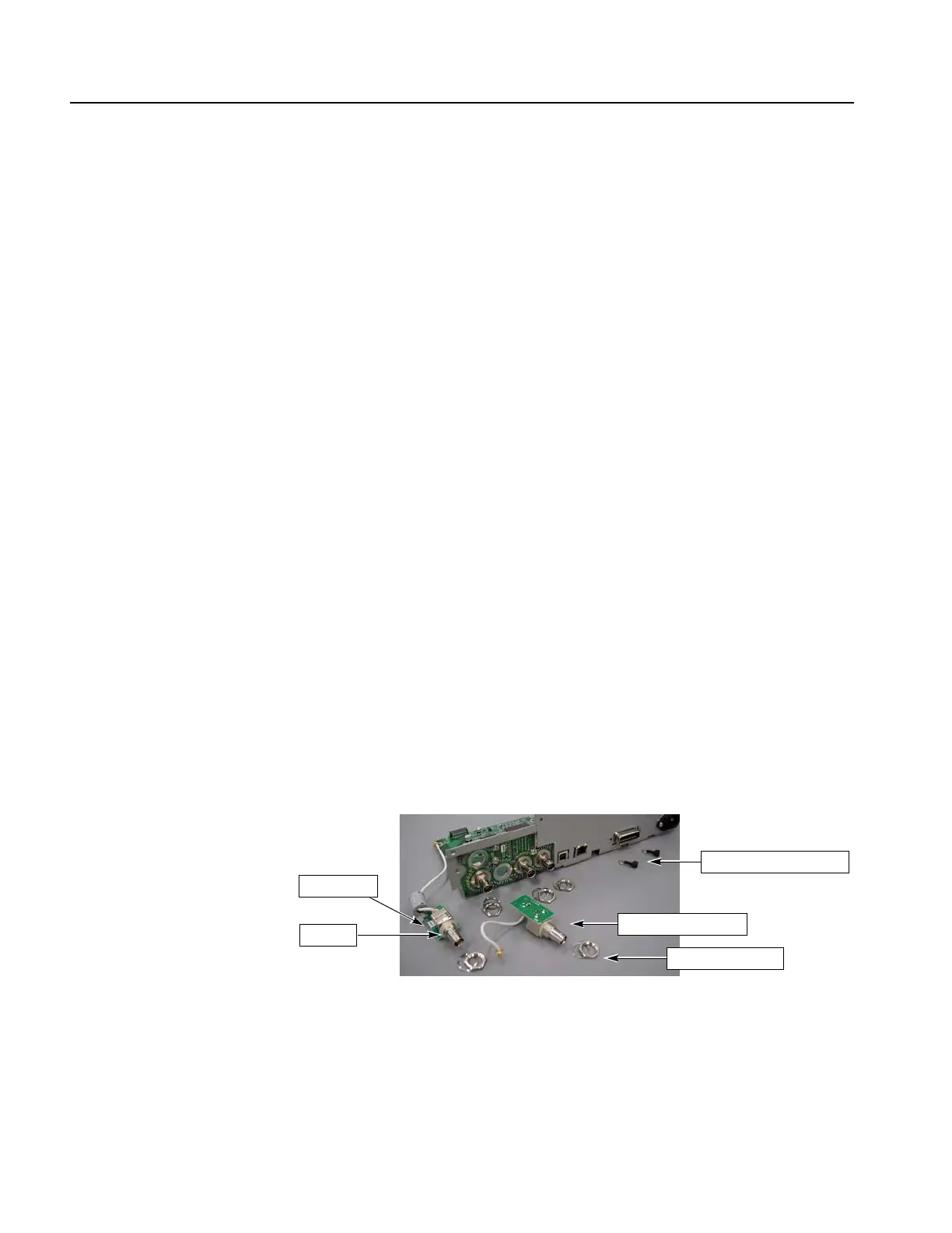
Figure 6-16: Remove the BNC connectors
5. Disconnect the AC input cable at J860 on the CPU board.
6. Disconnect the A75 Key Board cable at J300 on the CPU board.
CH1 Add Input
EXT Modulation CH2 Input
GPIB hex screws and washers
Insulator
Nut and spring washer
 Loading...


