1. Install the test hookup and preset the instrument controls:
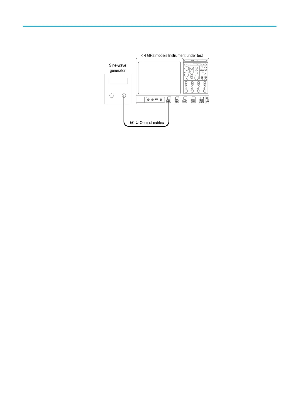
Figure 44: Serial trigger clock recovery range test hookup, <4 GHz Models
a. Hook up test-signal source 1: (See Figure 44: Serial trigger clock
recovery range test hookup, <4 GHz Models on page 278.)
■
Connect the sine wave output of the sine-wave generator through a
50 Ω precision coaxial cable to Ch 1 through an adapter.
■
Set the sine-wave generator to output a 1.5625 GHz sine wave.
b. Initialize the instrument: Press the Default Setup button.
c. Modify the initialized front-panel control settings:
■
Set the Vertical Scale to 50 mV per division.
■
Touch Vertical, select Vertical Setup, and then touch Termination
50 Ω.
■
Set the horizontal Scale to 200 ps per division.
■
From the button bar, touch the Display button.
■
Set the Display Style to Dots.
■
Set the Display Persistence to Variable, and set the persist Time to
3.0 s.
■
Touch the X (close) button.
■
Adjust the sine-wave generator output for 8 divisions of amplitude.
■
From the button bar, touch Trig and select the A Event tab.
■
Touch the Select button.
■
Touch the Comm button. Set Source to Ch1, Type to R Clk, and
Coding to NRZ.
2. Verify the clock recovery at frequency:
a. From the button bar, touch Trig and select the A Event tab.
b. Set the sine-wave generator to output one of the input frequencies in the
table that is not yet checked, starting with the first setting. (See Table 21:
Clock recovery input frequencies and baud rates on page 279.)
Performance verification (MSO/DPO70000C, MSO/DPO70000DX, and DPO7000C series)
278 MSO70000C/DX, DPO70000C/DX, DPO7000C, MSO5000/B, DPO5000/B Series
 Loading...


