To assemble the interlock:
1. Insert the wire into the CS-1616-3.
2. Use a pair of pliers to squeeze the connector sections together.
You cannot disassemble and reuse the CS-1616-3.
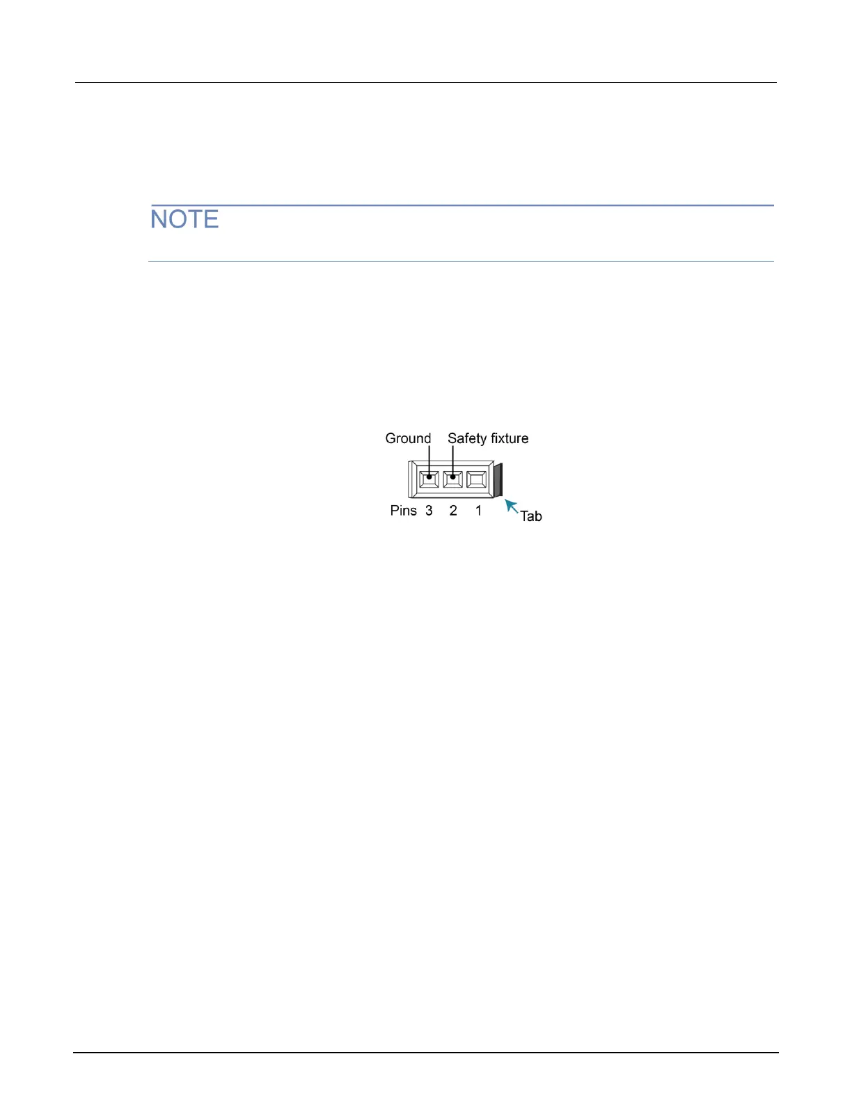
The interlock pin locations and connections are shown in the following figure. The pins are:
• Pin 3: Earth and chassis ground
• Pin 2: Interlock
• Pin 1 (next to tab): +6 V dc out (current limited)
Figure 27: Interlock mating connector pins
System information
You can retrieve serial number, firmware revision, calibration dates, and memory usage
from the instrument.
To view the system information from the front panel:
1. Press the MENU key.
2. Select SYSTEM-INFO.
3. Select one of the following:
▪ FIRMWARE
▪ SERIAL#
▪ CAL
▪ MEMORY-USAGE

 Loading...


