EasyManuals Logo
Home>Tektronix>Measuring Instruments>Keithley 2601B-PULSE

Tektronix Keithley 2601B-PULSE User Manual

Tektronix Keithley 2601B-PULSE
133 pages
To Next Page IconTo Next Page
To Previous Page IconTo Previous Page
Page #98 background imageLoading...
Page #98 background image
Section 4: Operation Model 2601B-PULSE System SourceMeter® Instrument User's Manual
4-8 2601B-PULSE-900-01 Rev. A August 2021
When the SMU or pulser is sourcing current, you can measure voltage or current, as shown in the
following figure.
Figure 42: Fundamental source-measure configuration: Source I
A
Current meter
Current source
V
Voltage meter
See “Basic circuit configurations” in the Model 2601B-PULSE Reference Manual for
detailed information.
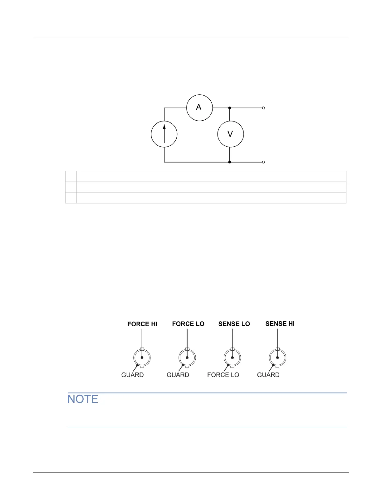
FORCE and SENSE connectors
You make connections from the instrument to the device under test (DUT) using the BNC connections
on the 2601B-P-INT.
The FORCE HI, FORCE LO, and SENSE HI connectors of the 2601B-P-INT have GUARD on the
shell. The SENSE LO connector has FORCE LO on the shell.
Figure 43: 2601B-P-INT FORCE and SENSE shell connections
The FORCE LO shell connection is for shielding only and should not be used to carry signal. Use the
center pin of the FORCE LO connector to carry signal.

Table of Contents

Other manuals for Tektronix Keithley 2601B-PULSE

Questions and Answers:

Question and Answer IconNeed help?

Do you have a question about the Tektronix Keithley 2601B-PULSE and is the answer not in the manual?

Tektronix Keithley 2601B-PULSE Specifications

General IconGeneral
BrandTektronix
ModelKeithley 2601B-PULSE
CategoryMeasuring Instruments
LanguageEnglish

Related product manuals