• To add a new Bus badge on the Settings bar, tap the Add Math Ref Bus button and select Bus. This adds the Bus badge to the
Settings bar .
•
Double-tap the Bus badge. This opens the Bus configuration menu
x
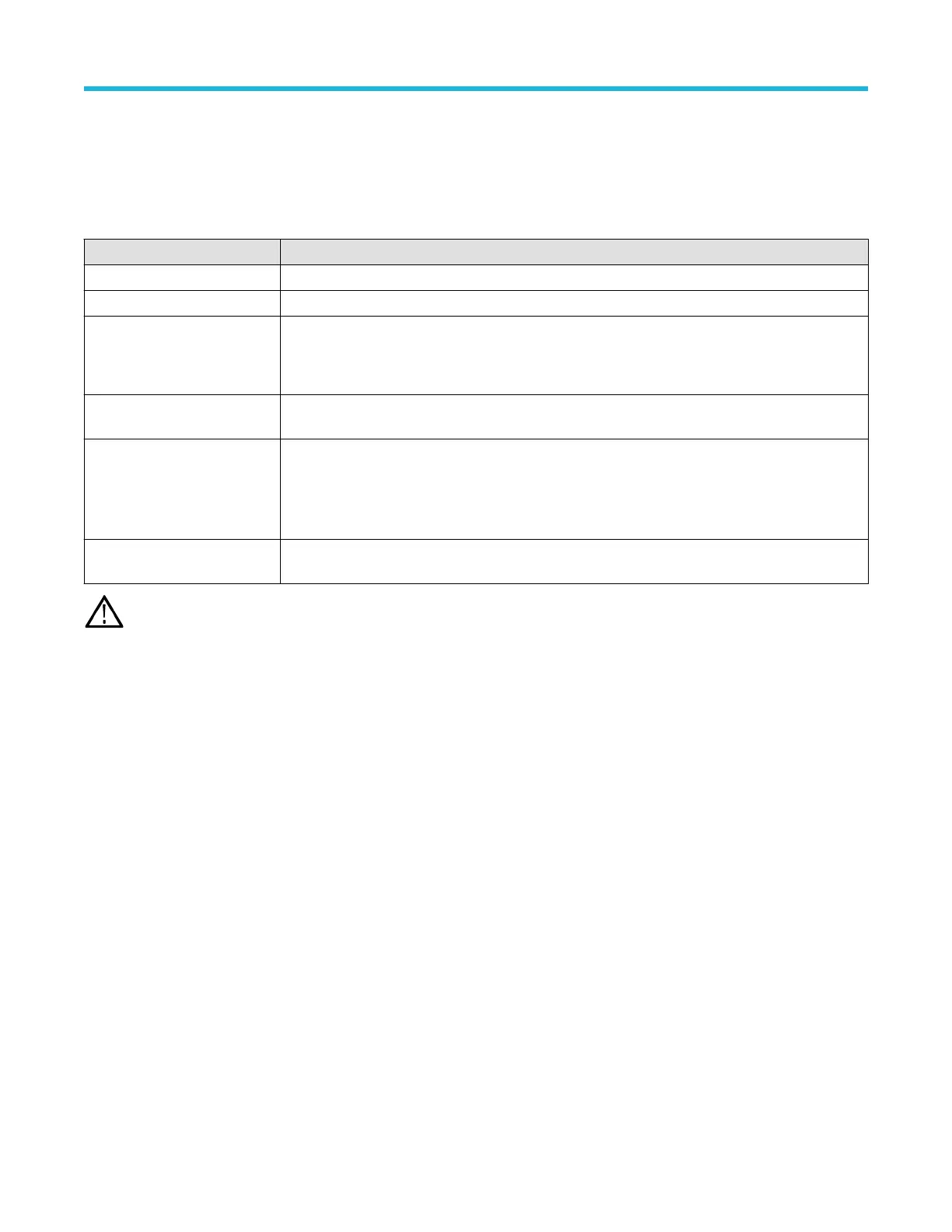
Bus configuration menu - fields and controls
Field or control Description
Display Toggles bus display on or off.
Label Allows entry of label text in this field. The default label is the bus type.
Bus Type Select a bus from the drop down list. The Parallel bus type comes standard on the instrument. Serial
buses require purchase and installation of serial bus triggering and analysis options.
See Serial bus decode and trigger options on page 26.
Source configuration Specifies the bus signal input parameters. Shown fields depend on the selected bus type. See the
individual bus configuration help topics for information on their settings.
Display format Enables showing just the decoded bus or both the bus and its digital subwaveforms. You can also tap
on the + symbol on the bus waveform to toggle between showing the bus only or showing bus and
source waveforms. Digital waveforms represent the logical waveforms for each signal after they have
been digitized. If the decode is not working as expected, you can look at the individual waveforms to
see if things like suboptimal threshold settings are causing incorrect decoding.
Decode format Sets how decoded data information is shown in the bus. Select from listed formats. Available formats
depend on the bus type.
Note: These controls are common to all bus types. Controls unique to specific bus types are discussed in separate topics for each
bus.
Other bus types
Serial bus types, such as CAN, LIN, Ethernet, and so on, are available as purchasable options. Once purchased and installed, the new bus
types are shown in the Bus T
ype menu. The serial bus options also add corresponding bus trigger capabilities to the Trigger menu.
Use the following links to access information on specific Bus configuration menus.
Parallel Bus configuration menu on page 127
I2C serial bus configuration menu on page 123
SPI serial bus configuration menu on page 131
RS-232 serial bus menu on page 129
CAN serial bus configuration menu on page 120
LIN serial bus configuration menu on page 124
FlexRay serial bus configuration menu on page 122
Audio serial bus configuration menu on page 118
USB serial bus configuration menu on page 132
MIL-STD-1553 serial bus menu on page 126
ARINC429 serial bus menu on page 117
Menus and dialog boxes
3 Series Mixed Domain Oscilloscope Printable Help 116
 Loading...


