Where: x(i) is the source waveform, y(n) is a point in the integral math waveform, scale is the output scale factor
, and T is the time
between samples.
Since the resultant math waveform is an integral waveform, its vertical scale is in volt-seconds (its horizontal scale is in seconds). The
source signal is integrated over its entire record length; therefore, the math waveform record length equals that of the source waveform.
Offset and position
When creating integrated math waveforms from live channel waveforms, consider the following:
• You should scale and position the source waveform so that it is contained on screen. (Off screen waveforms may be clipped, which will
result in errors in the integral waveform.)
• You can use vertical position and vertical offset to position your source waveform. The vertical position and vertical offset will not affect
your integral waveform unless you position the source waveform off screen so that it is clipped.
DC offset
The source waveforms that you connect to the instrument often have a DC offset component. The instrument integrates this offset along
with the time-varying portions of your waveform. Even a few divisions of offset in the source waveform may be enough to ensure that the
integral waveform saturates (clips), especially with long record lengths.
Using math waveforms
This topic helps you create basic math waveforms.
Create math waveforms to support the analysis of your channel and reference waveforms. By combining and transforming source
waveforms and other data into math waveforms, you can derive the data view that your application requires.
Note: Math waveforms are not available for use with serial buses.
Math functions are available when the instrument is operating in time-domain mode.
Use the following procedure for executing basic (+, –, x, ÷) math operations on two waveforms:
1. T
ap the Add Math Ref Bus button and then tap Math. This creates a Math badge and displays the math waveform.
2. Double-tap the Math badge to open the Math configuration menu.
3. Tap the Math Type Basic button.
4. Set the sources to either channel 1, 2, 3, 4, or reference waveforms R1, 2, 3, or 4.
5. Choose the +, –, x, or ÷ operators.
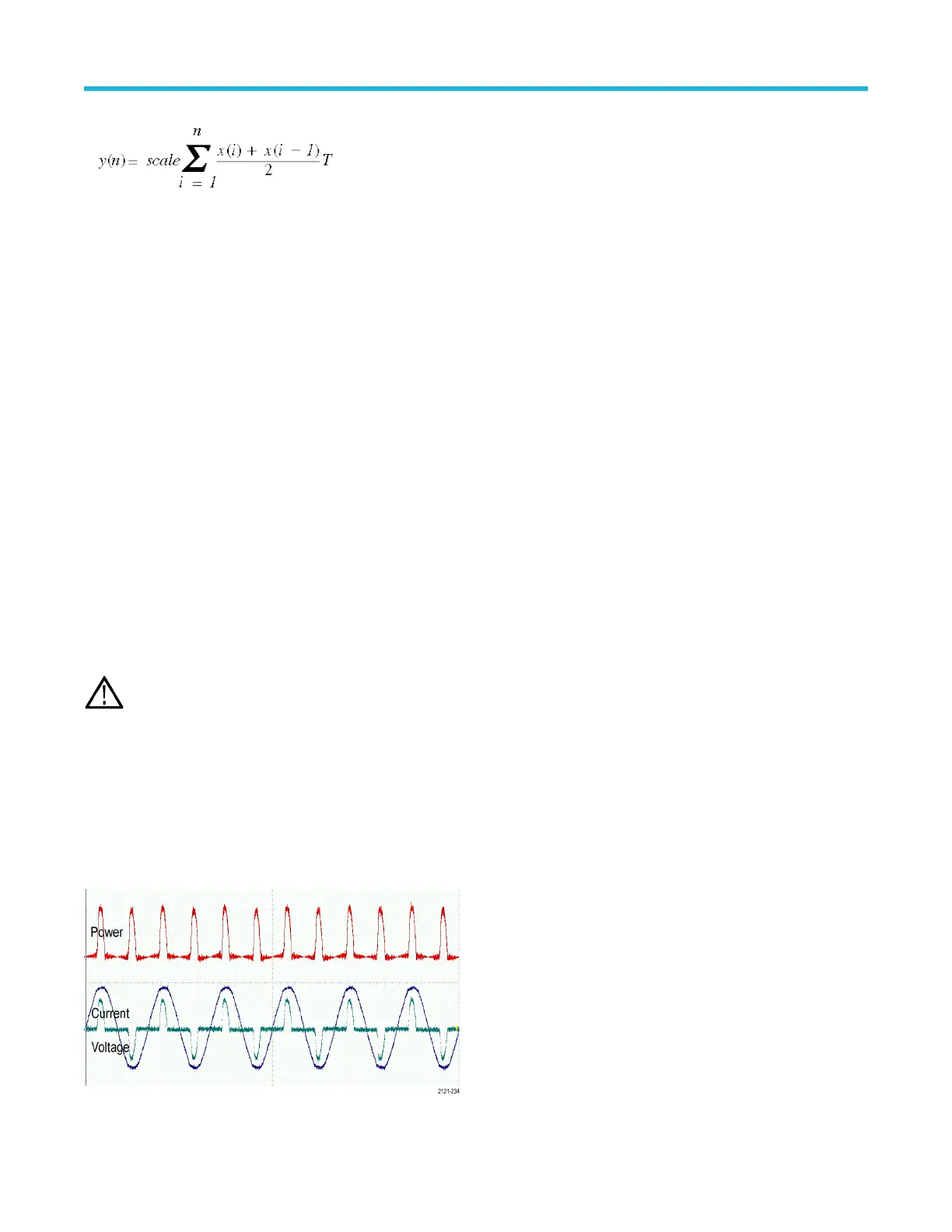
6. For example, you might calculate power by multiplying a voltage waveform and a current waveform.
Measurement concepts
3 Series Mixed Domain Oscilloscope Printable Help 265
 Loading...


