Troubleshooting
6-- 56
TDS7104 & TDS7054 Service Manual
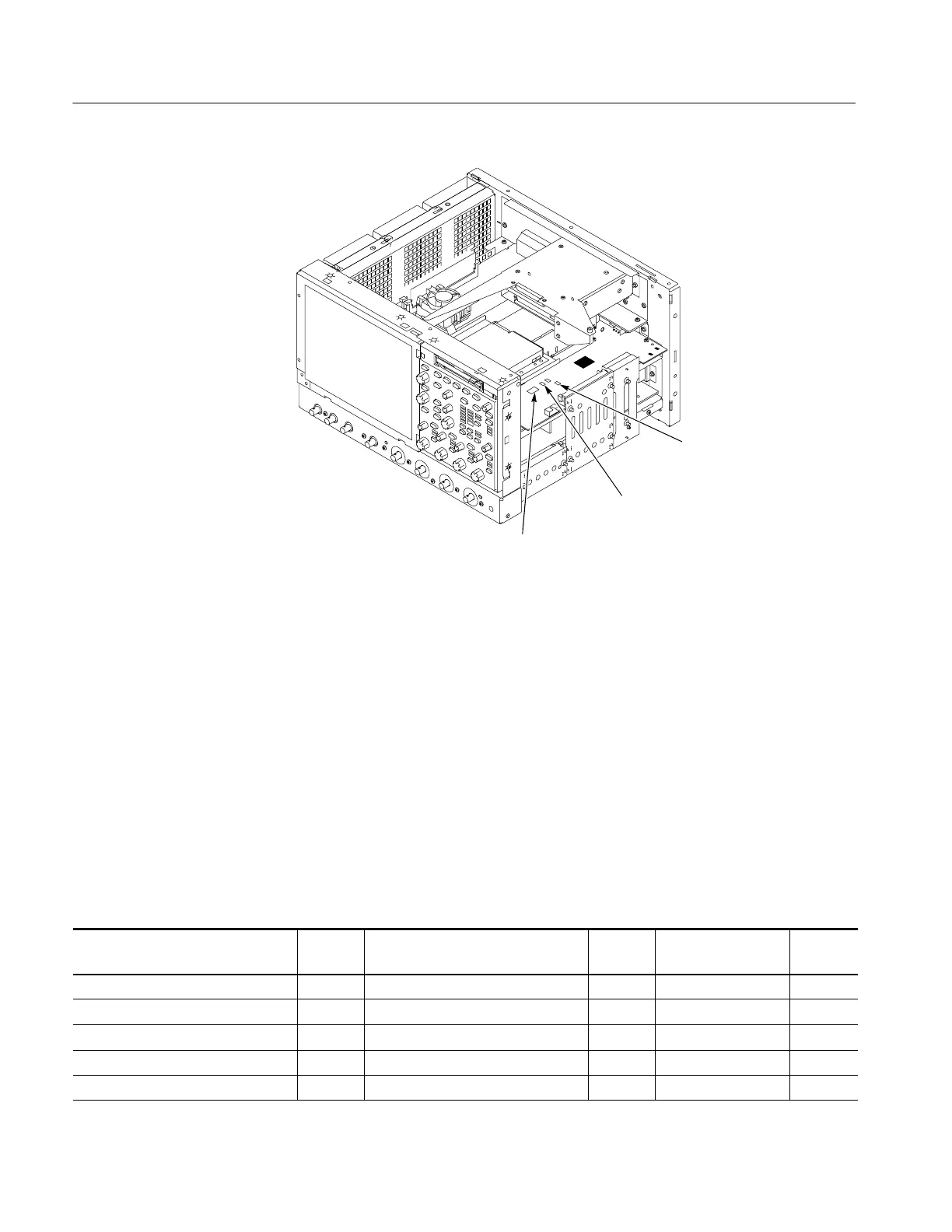
Debug
RST
Debug VSB5
Debug
Power-On
Figure 6--32: Location of debug pins
To check the power supply voltages, power on the oscilloscope and connect the
reference lead of a digital voltmeter to chassis ground, such as the top of the
power supply.
Attach a 0.025 inch square pin to the probe tip of the other lead and insert it into
a pin on one of the connectors. The pins that should be carrying voltages are
listed in Table 6--5. The location of the J1 and J2 connectors is shown in
Figure 6--33 on page 6--57.
Measure the power supply voltages with the voltmeter and compare each reading
to the values listed in the tables. If the voltages are within about 5% of the
nominal voltages, your power supply is functional.
Table 6--5: Power supply voltages
Front power distribution board
(P2) and Power supply (J2)
Voltage
Rear power distribution board
(P1) and Power supply (J1)
Voltage Riser board Voltage
PinsA/B/C1,3,5,7,9,11 +3.3 V Pins A/B/C5, 6 +12 V Pin B 170 -- 5 V
Pins A/B/C13 -- 1 5 V Pins A/B/C8, 9, 11, 12, 14, 15, 17 +5 V Pin A1 -- 1 2 V
Pins A/B/C15 +15 V Pins A/B/C19, 21, 23, 25, 27, 29, 31 +3.3 V Pin B2 +12 V
Pins A/B/C17, 18, 20, 21, 22 -- 5 V Pins B/C3 (fan voltage) +9.8 V Pin A5 +3.3 V
Pins A/B/C24, 25, 27, 28, 30, 31 +5 V Pin A57 +5 V
Checking the Power
Supply Voltages
 Loading...

