Operating Information
2-10
TDS7104 & TDS7054 Service Manual
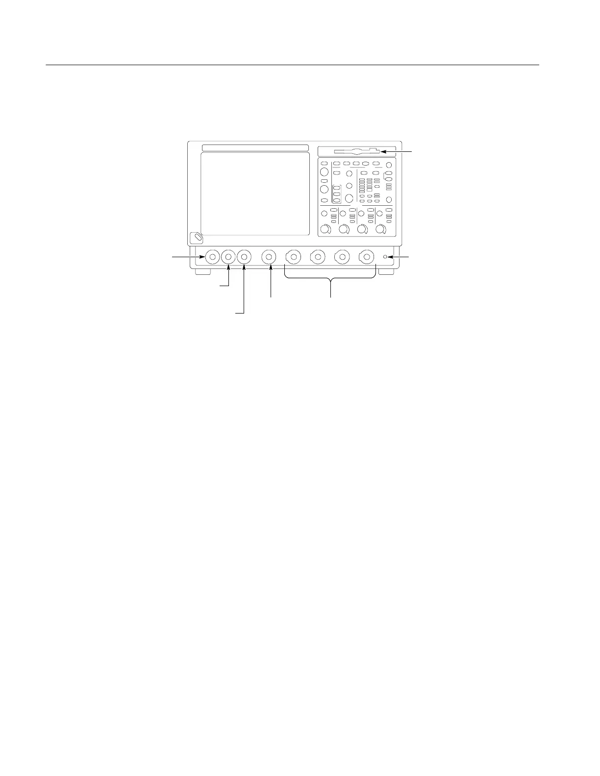
The following illustration shows the input/output connectors and floppy disk
drive location.
Floppy disk drive
Auxiliary trigger input
Auxiliary
trigger output
CH 3 SIGNAL
OUTPUT; scale and
offset controlled by
CH3 controls
Probe
compensation
output
Ground terminal
Channel
inputs
Do the following steps to verify the instrument passes the internal diagnostics.
1. Display the diagnostics menu:
H If the oscilloscope is in tool bar mode, touch the MENU button to put
the oscilloscope into the menu bar mode.
H Select Instrument Diagnostics . . . .from the Utility menu.
2. Run the diagnostics.
H First disconnect any input signals from all four channels.
H Touch the Run button in the diagnostics control window.
3. Wait for the diagnostics to complete.
The internal diagnostics do an exhaustive verification of proper
oscilloscope function. This verification may take several minutes to
complete. When the verification is finished, the resulting status will
appear in the diagnostics control window.
4. Verify that no failures are found.
Run the Signal Path Compensation.
1. Select Instrument Calibration . . . from the Utility menu.
Front Panel I/O Map
Instrument Diagnostics
Signal Path Compensation
 Loading...

