DIGGER DERRICK
1-27
Digger Derrick Terex South Dakota, Inc. 463280 - 9/14
OPERATION GUIDELINES
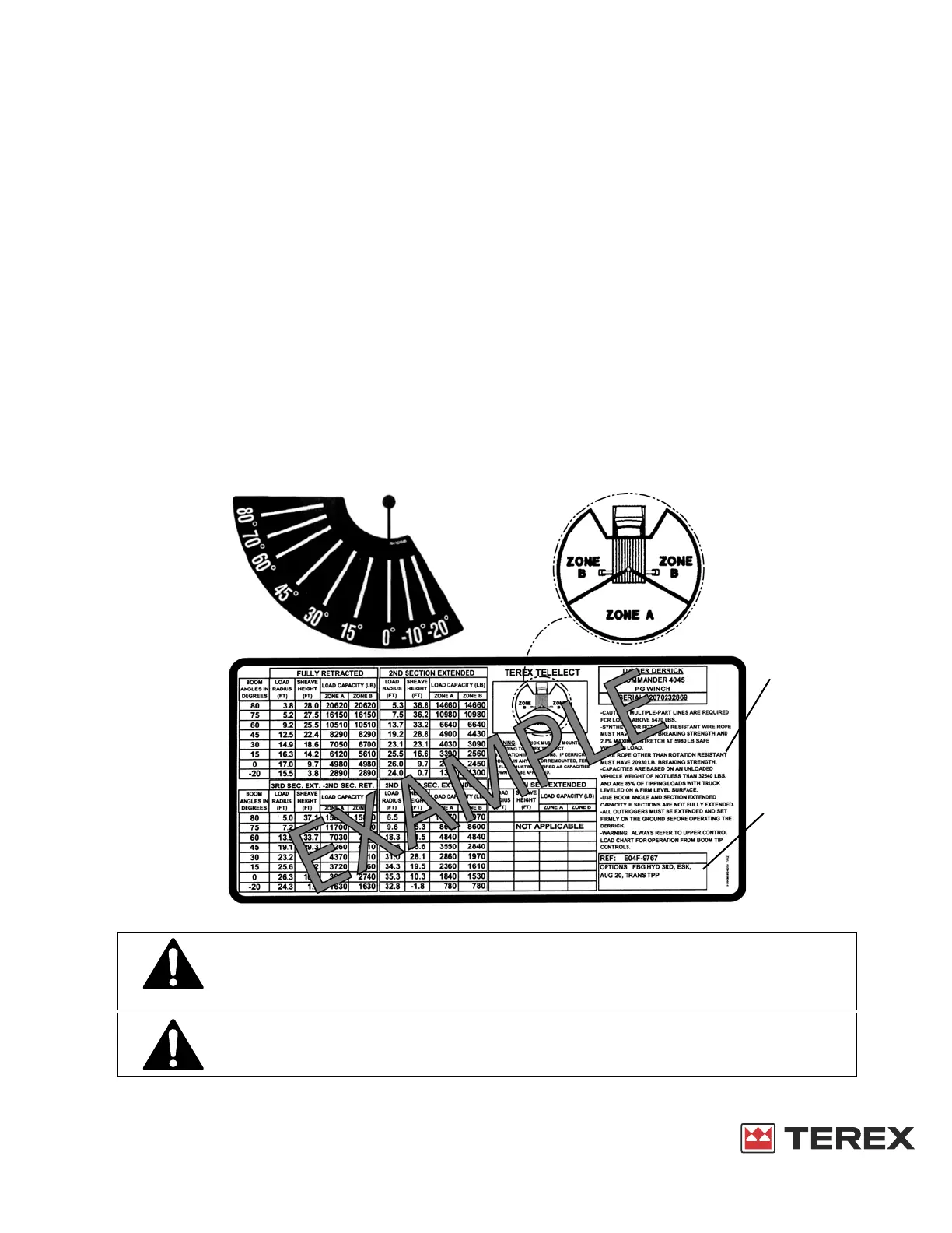
LOAD CHART
The load chart at the operator station provides the load capacities of the Digger Derrick when lifting a freely
suspended load. The load chart gives allowable loads when the vehicle is level. If not level, the capacity is
reduced.
The capacity of the unit is determined by five items:
1. The rope capacity (shown on the right upper side of the load chart).
2. The boom angle (If between angles use the lower angle).
3. The boom extension. (Consider extended if not fully retracted.)
4. Rotational position relative to the truck. (Zone A or B).
5. Jib capacity (if used is shown on separate chart).
6. Options.
The allowable load will be the lowest load permitted by the rope capacity, Load Capacity Chart, or Jib
Capacity Chart. The Load Capacity Chart only gives the boom capacity, the load line may have to be multi-
parted to lift the capacity shown.
Attempting to lift unknown loads may overload the unit or cause instability. Poles and items embedded in the
ground, attached, or frozen to the ground are unknown weights that may overload the structure and may
cause structural damage or overturning.
ANGLE INDICATOR AND LOAD CAPACITY CHART DECAL
NOTE: All units must have a load chart for the specific serial number. Also the boom angle
indicator must be functional.
Complying with the Load Capacity Chart is very important for safe operation. If
missing, illegible or damaged replace immediately. Do not assume capacity is the
same as other units. Each Load Capacity Chart is only for the Digger Derrick serial
number shown on the chart.
The weight of the slings, rigging, and lifting attachments are part of the gross load
being lifted and must be included in the load weight. All rigging must have
sufficient capacity for total load being lifted.
 Loading...