3.2.1 Over Voltage and Under Voltage Protection Circuit
The voltage protection circuit on the EVM protects the board from overvoltage, under voltage and transient
voltage input cases. The safe operation input voltage range is 6 V to 28 V. A fault indication and power good
LEDs are provided to indicate the power status.
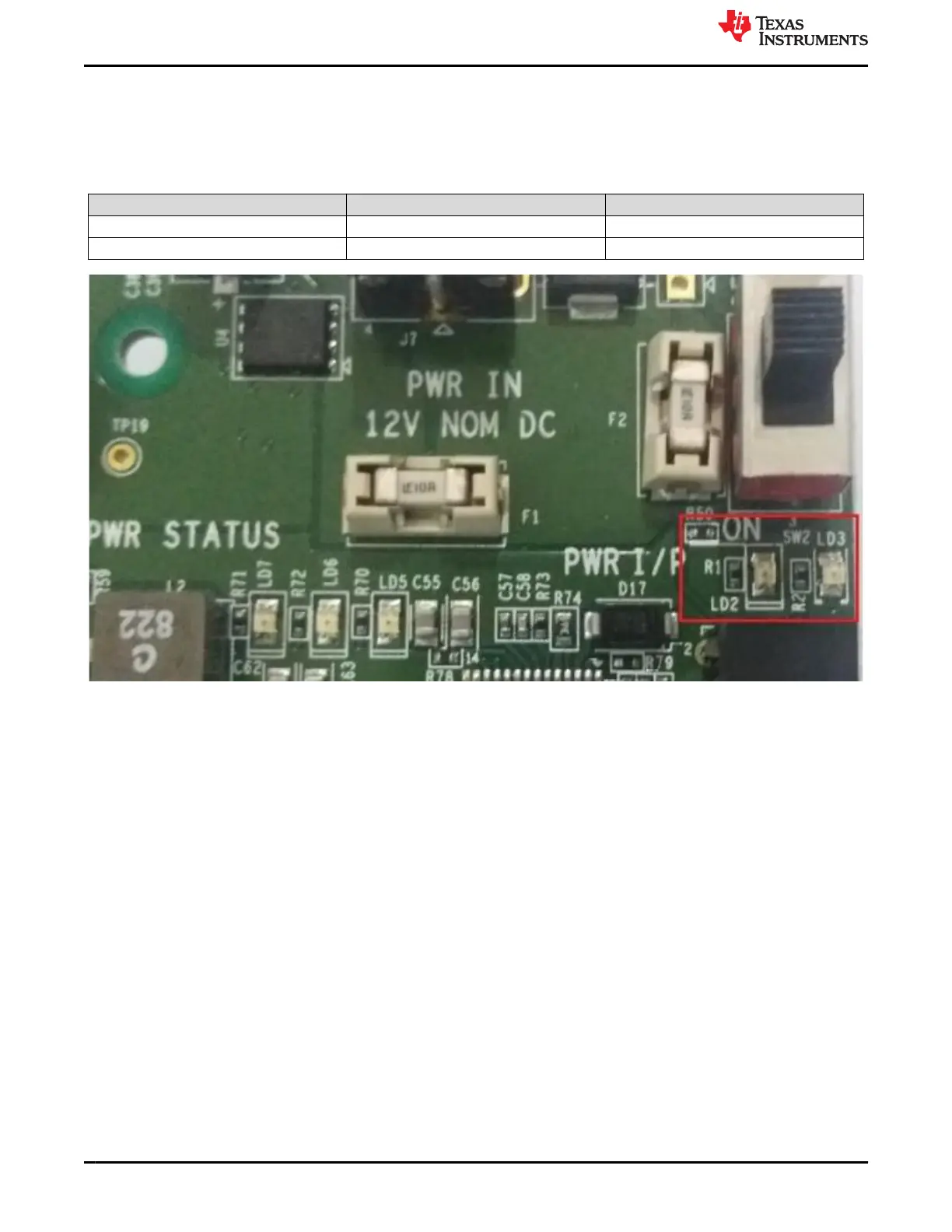
Table 3-2. Power LED Status
LED ON Status OFF Status
LD2 Board Power on Board Power off
LD3 Input voltage is >28 V or <6 V Input voltage is within the limit
Figure 3-3. Power ON/Fault LEDs
EVM User Setup/Configuration www.ti.com
14 Jacinto7 J721E/DRA829/TDA4VM Evaluation Module (EVM) SPRUIS4D – MAY 2020 – REVISED MARCH 2022
Submit Document Feedback
Copyright © 2022 Texas Instruments Incorporated
 Loading...


