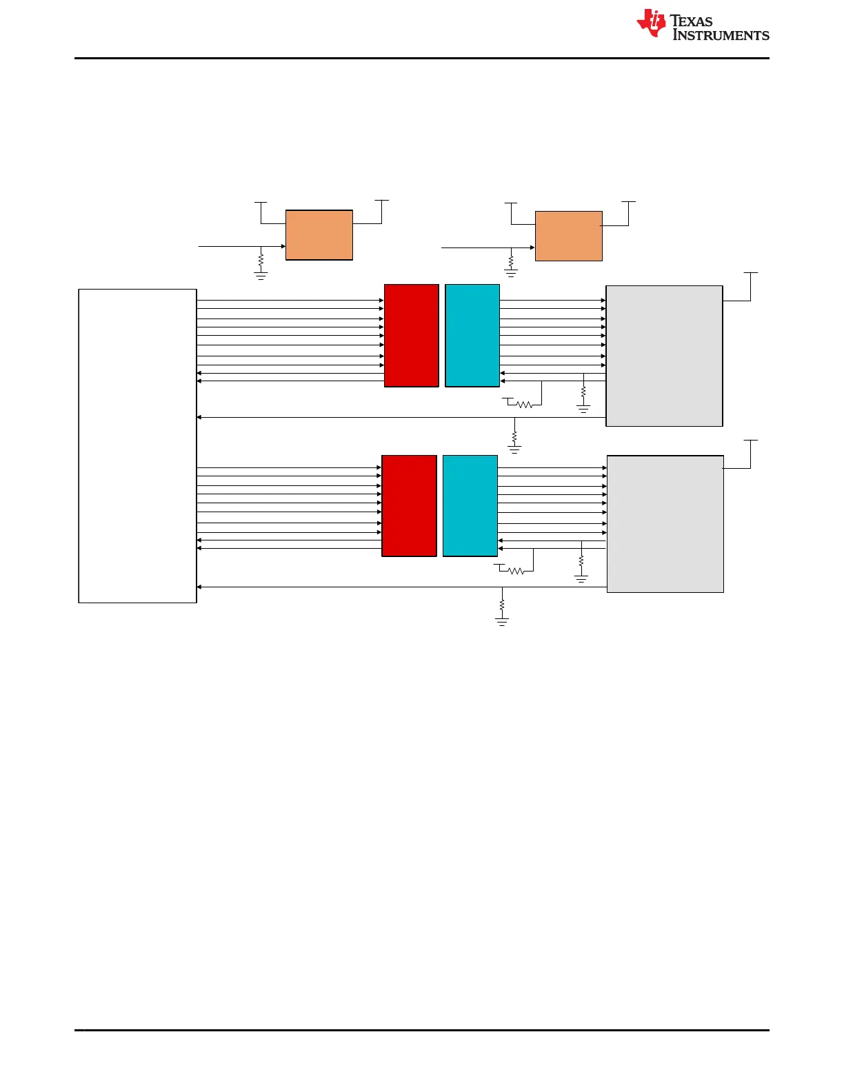
4.18 Display Port Interface
Common Processor Board supports two display port interfaces DP0 and DP1. However, J721E SoC supports
only DP0. DP1 shall be available on CP board to support future J7 SoC. Display port is connected to Torrent
SERDES (SERDES4) internal to J721E SoC. 4K UHD Display (3840 x 2160) @ 120 Hz (MST- Multi stream
support), up to Two 4K UHD Displays (3840 x 2160) @ 60 Hz (MST) can be supported by CP board display port
interface. Standard full-size Molex display connector Mfr. Part# 472720001 is used to interface with displays.
J721E
SoM
Common
Mode
Chokes
(MCZ1210D
H900L2TAD
Gx5)
ESD
Devices
(TPD1E05U
06DPYx10)
Common
Mode
Chokes
(MCZ1210D
H900L2TAD
Gx5)
ESD
Devices
(TPD1E05U
06DPYx10)
LDO
TPS74801DRCR
LDO
TPS74801DRCR
Display Port
Connector
472720001
Display Port
Connector
472720001
100k
100k
100k
100k
100k
100k
VSYS_3V3
V3V3_DP0
VSYS_3V3
V3V3_DP1
DP0_PWR_SW_EN
I2C GPIO EXPANDER4, P0
I2C ADD# 0X20
I2C GPIO EXPANDER4, P0
I2C ADD# 0X20
DP1_PWR_SW_EN
DP0_HPD
DP1_HPD
DP0_TX0_P
DP0_TX0_N
DP0_TX1_P
DP0_TX1_N
DP0_TX2_P
DP0_TX2_N
DP0_TX3_P
DP0_TX3_N
DP0_AUXP
DP0_AUXN
DP0_TX0_P
DP0_TX0_N
DP0_TX1_P
DP0_TX1_N
DP0_TX2_P
DP0_TX2_N
DP0_TX3_P
DP0_TX3_N
DP0_AUXP
DP0_AUXN
DP1_TX0_P
DP1_TX0_N
DP1_TX1_P
DP1_TX1_N
DP1_TX2_P
DP1_TX2_N
DP1_TX3_P
DP1_TX3_N
DP1_AUXP
DP1_AUXN
DP1_TX0_P
DP1_TX0_N
DP1_TX1_P
DP1_TX1_N
DP1_TX2_P
DP1_TX2_N
DP1_TX3_P
DP1_TX3_N
DP1_AUXP
DP1_AUXN
VSYS_3V3
VSYS_3V3
V3V3_DP0
V3V3_DP1
Figure 4-38. Display Port Block Diagram
Separate ESD protection devices of Mfr. Part# TPD1E05U06DPY are used for main and auxiliary data channels
and Common mode filters MCZ1210DH900L2TA0G at every differential data and aux pairs. Supply 3.3 V, 500
mA for each connector has been given through individual LDOs Mfr. Part# TPS74801DRCR. The LDO has
active high enable input and is disabled by default. Driving high from GPIO from I/O Expander4 (I2C ADD# 0x20)
Port0 and Port1 will enable the supplies to Display Port connectors.
4.19 MLB Interface
Common Processor board supports for Media Local Bus (MLB) interface.
Differential pairs of MLB signals from J721E SoC are routed to Samtec header Mfr. Part# QSH-020-01-L-D-DP-
A-K. This interfaces is designed to mate with MicroChip’s MLB Physical interface board. The differential signals
are routed with a characteristic impedance of 100E and also a Pull up and Pull-down option is provided for the N
and P signals respectively. The reset signal that comes from the expander (I2C ADD# 0x22, I2C0) is availed with
a pull down to avoid floating, and the interrupt signal is equipped with a pull up and routed to J721E SoM.
The 12 V and 3.3 V are drawn from the CP board to the connector; the I2C control is provided to the MLB
Header from I2C0 port of J721E SoC.
J721E EVM Hardware Architecture www.ti.com
68 Jacinto7 J721E/DRA829/TDA4VM Evaluation Module (EVM) SPRUIS4D – MAY 2020 – REVISED MARCH 2022
Submit Document Feedback
Copyright © 2022 Texas Instruments Incorporated
 Loading...


