4.5 Power Supply
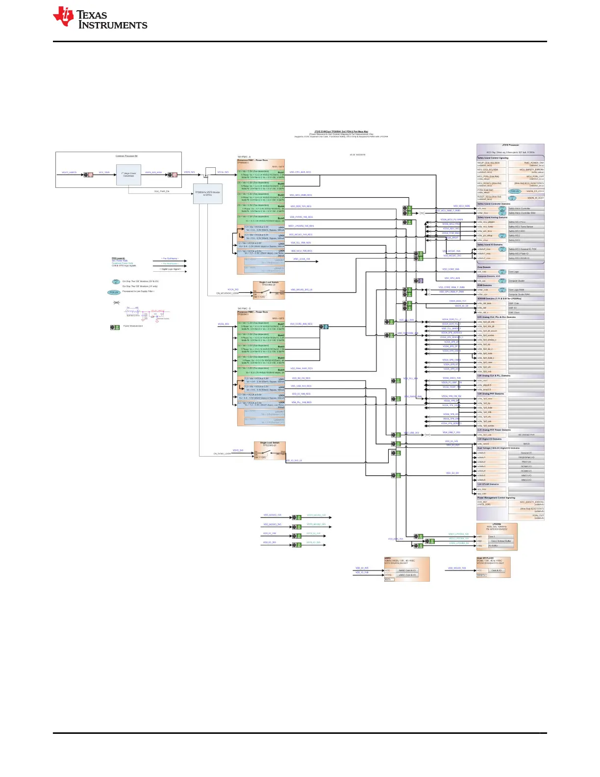
Figure 4-3 shows the SoM’s power distribution system. The Power to the SoM is derived from the Dual Buck
converter 12 V to 5.0 V / 3.3 V on the Common Processor Board. The J721E processor is powered from a dual
TPS6594x PMIC solution, which is optimized for the J721E to support a wide variety of use cases.
Dual load switch TPS22976-Q1 provides the switching option for the LPDDR4 I/O power supply (1.1 V / 0.6 V).
Figure 4-3. J721E SOM Power Distribution Block Diagram
www.ti.com J721E EVM Hardware Architecture
SPRUIS4D – MAY 2020 – REVISED MARCH 2022
Submit Document Feedback
Jacinto7 J721E/DRA829/TDA4VM Evaluation Module (EVM) 31
Copyright © 2022 Texas Instruments Incorporated
 Loading...


