Table 4-26. ADC Header J23 Pinout
Pin No Signal Pin No Signal
1 DGND 2 MCU_ADC0_AIN3
3 MCU_ADC0_AIN7 4 MCU_ADC0_AIN0
5 MCU_ADC0_AIN1 6 MCU_ADC0_AIN6
7 DGND 8 DGND
9 MCU_ADC0_AIN4 10 MCU_ADC0_REF_P
11 MCU_ADC0_AIN2 12 MCU_ADC0_REF_N
13 DGND 14 DGND
15 MCU_ADC0_AIN5 16 MCU_ADC_EXT_TRIGGER0
17 NC 18 NC
19 DGND 20 DGND
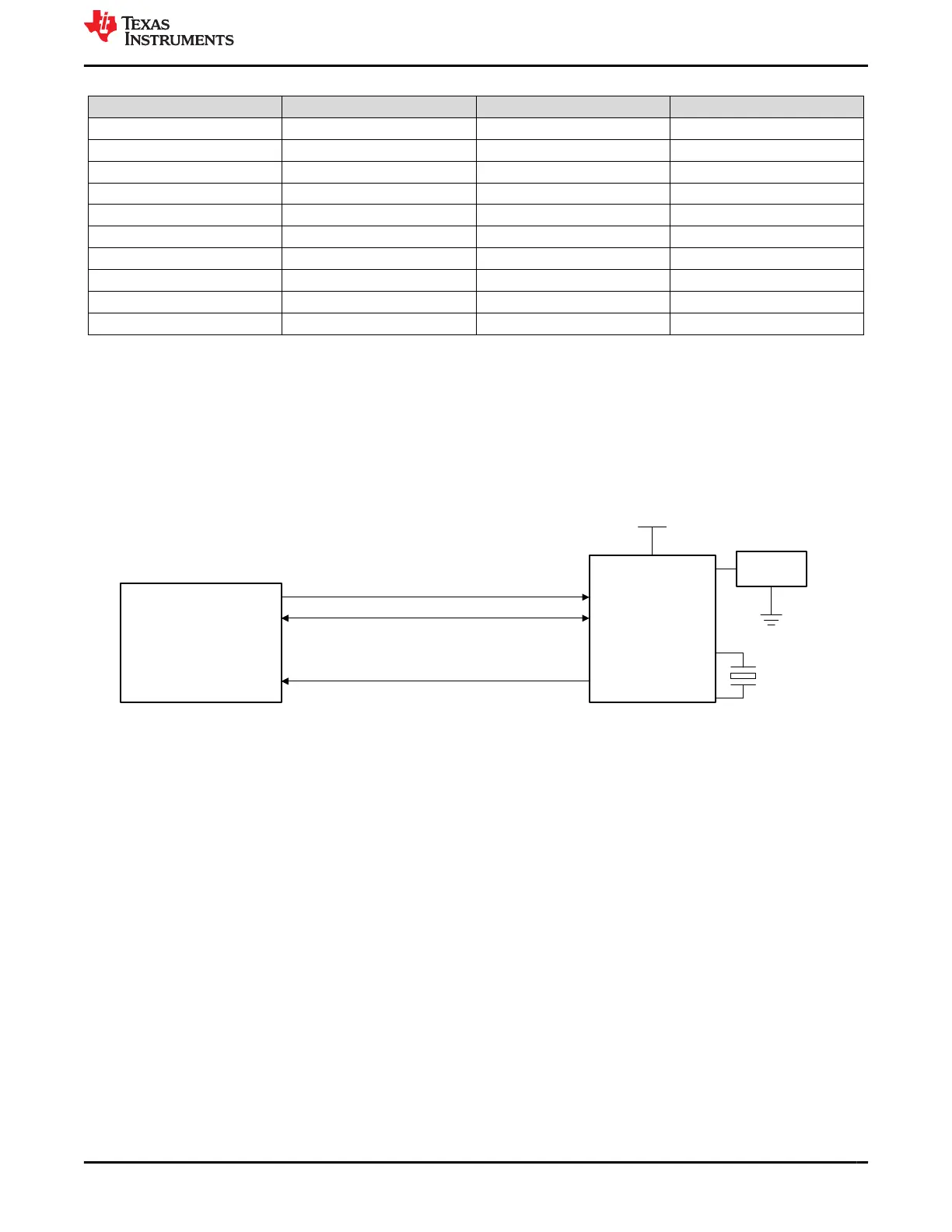
4.22 RTC Interface
A real-time clock module Mfr. Part# MCP79410-I/SN is connected I2C0 interface of J721E SoC.
RTC device is being powered by 3.3 V and a battery holder BC501SM is connected to VBAT pin for external
battery power option (battery not provided). A 32.768 kHz quartz crystal is used to provide clock for the device.
MFP pin of RTC module is used to generate optional reference clock to the SoC’s WKUP_LFOSC.
7-bit I2C addresses are 0x57 and 0x6F.
J721E SOM
MCP79410
MFP
VBAT
I2C0_SCL
I2C0_SDA
RTC_REF_CLK
(BC501SM)
VSYS_IO_3V3
Battery
Holder
Figure 4-41. RTC Block Diagram
www.ti.com J721E EVM Hardware Architecture
SPRUIS4D – MAY 2020 – REVISED MARCH 2022
Submit Document Feedback
Jacinto7 J721E/DRA829/TDA4VM Evaluation Module (EVM) 71
Copyright © 2022 Texas Instruments Incorporated
 Loading...


