AccessingtheHydraulic
Pump
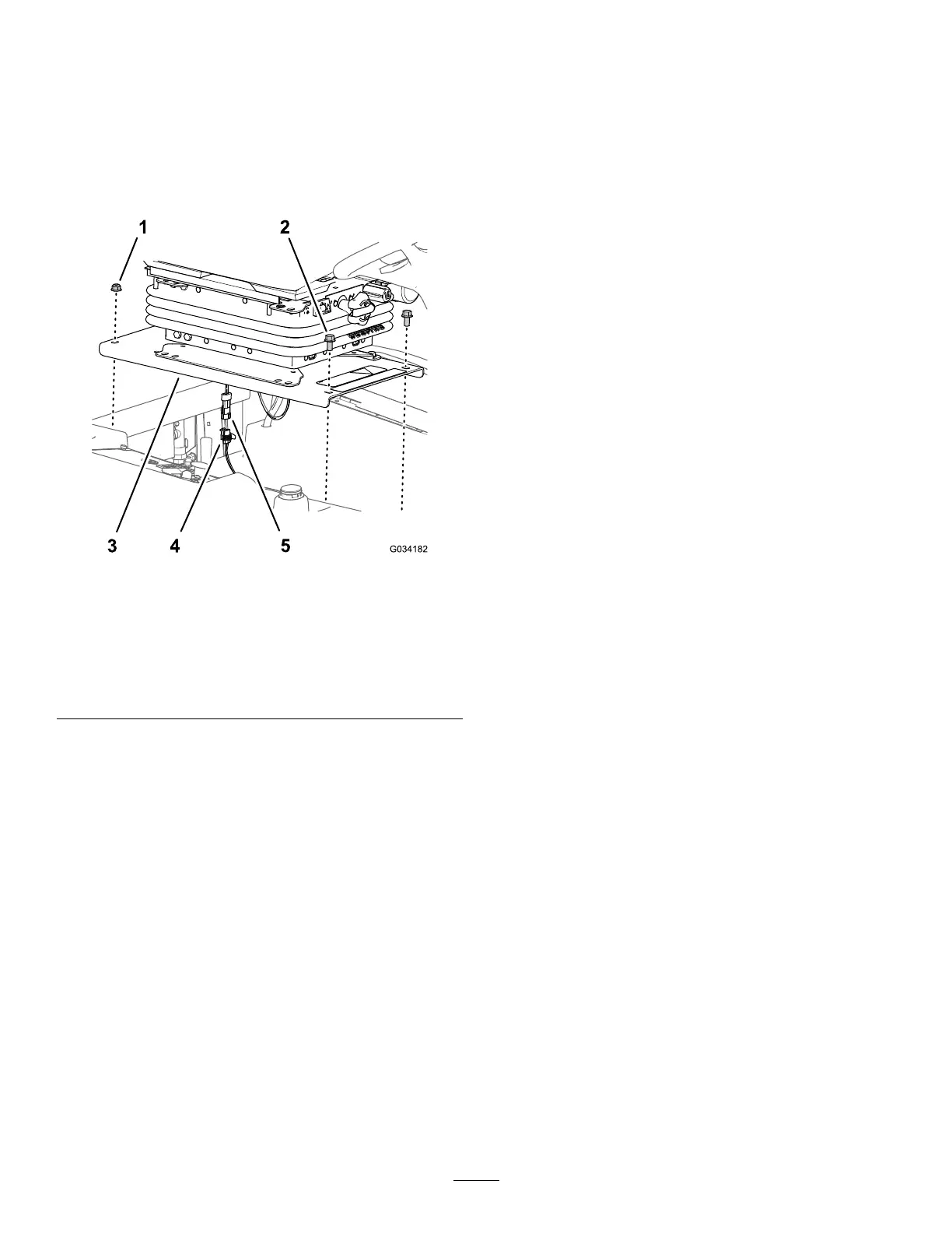
RemovingtheSeatandSeatPlate
1.Removethe2ange-headbolts(3/8x3/4inch)
atthethatsecurethefrontoftheseatplateto
thechassisofthemachine(Figure33).
g034182
Figure33
1.Flangelocknuts(3/8inch)
4.2-socketconnector
(machinewireharness)
2.Flange-headbolts(3/8x
3/4inch)
5.2-pinconnector
(operator-presenceswitch
harness)
3.Seatplate
2.Removethe2angelocknuts(3/8inch)atthe
thatsecurethebackoftheseatplatetothe
chassisofthemachine(Figure33).
3.Partiallylifttheseatassembly.
4.Disconnectthe2-pinconnectorforthe
operator-presenceswitchharnessfromthe
2-socketconnectorofthemachinewireharness
(Figure33).
5.Removetheseatassemblyfromthemachine.
InstallingtheSeatandSeatPlate
Installtheseatonceyouhaverepairedthemachine
andclosedthebypassvalveforthehydraulicpump.
1.Aligntheseatassemblytotheopeninginthe
fueltank.
2.Connectthe2-pinconnectorforthe
operator-presenceswitchharnessintothe
2-socketconnectorofthemachinewireharness;
refertoFigure33.
3.Aligntherearholesintheseatplate(Figure33)
withthe2carriagebolts(3/8x1inch)inthe
radiatorchannel.
4.Assembletheseatplate(Figure33)tothe
carriageboltswiththe2angelocknuts(3/8
inch)thatyouremovedinstep2ofRemoving
theSeatandSeatPlate(page39).
5.Alignthefrontholesintheseatplate(Figure33)
withthethreadsofthetankrods.
6.Assembletheseatplate(Figure33)tothetank
rodswiththe2ange-headbolts(3/8x3/4inch)
thatyouremovedinstep1ofRemovingthe
SeatandSeatPlate(page39).
7.Torquetheangelocknutsandange-head
boltsto37to45N∙m(27to33ft-lb).
8.Checktheinterlocksystem;refertoChecking
theInterlockSystem(page26).
39
 Loading...