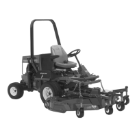
g035477
Figure66
1.Proximitysensor
5.Sensorbracket
2.Gap—2.5to3.6mm(0.10
to0.14inch)
6.Flange(neutralarm)
3.Rightsideofthemachine
7.Undertheseat
4.Jamnut
2.Loosenthejamnutsateithersideofthesensor
bracket(Figure66).
3.Adjustjamnutsuntilthereisa2.5to3.6
mm(0.10to0.14inch)gapbetweentheend
oftheproximitysensorandtheangeofthe
neutralarm(Figure66).
4.Tightenthejamnuts(Figure66).
FinishingtheTractionDrive
Adjustment
1.Removethejackstandsandlowerthemachine
totheground.
2.Installtheseatandseatplate;refertoInstalling
theSeatandSeatPlate(page39).
3.Testdrivethemachinetoensurethatitdoesnot
movewhenthetractionpedalisinneutral.
AdjustingtheSteering
Stops
4-WheelDriveMachinesOnly
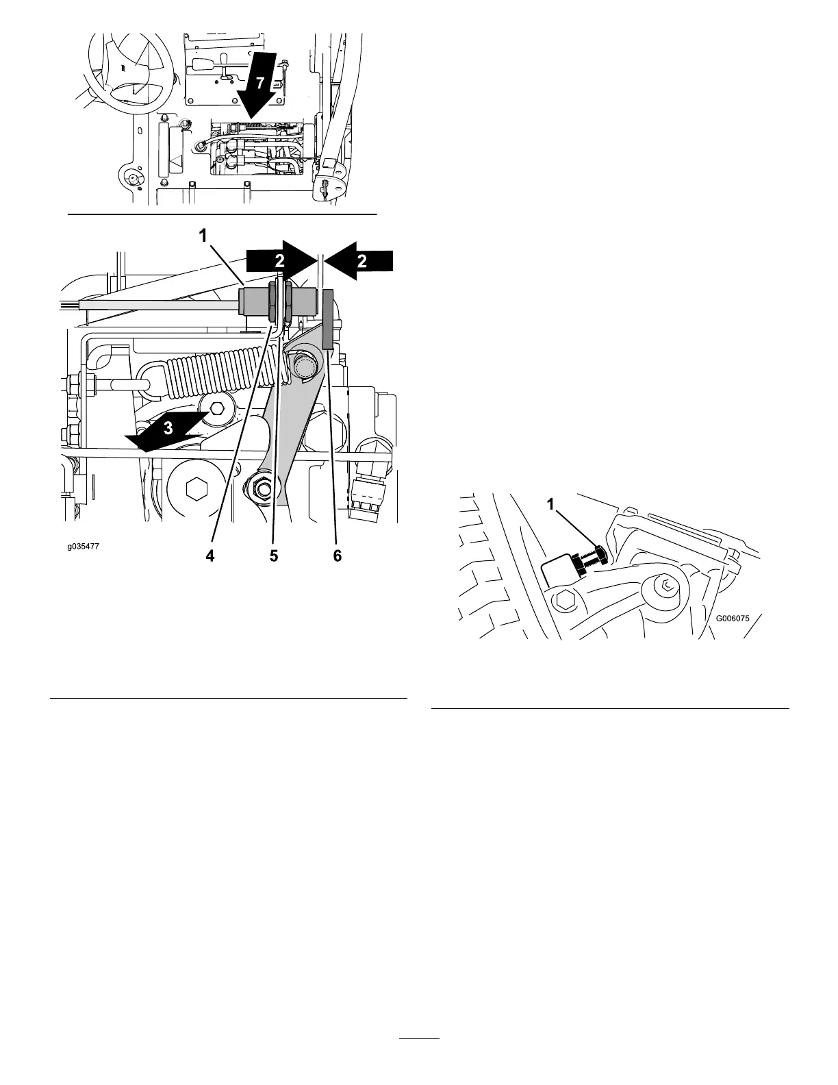
Therear-axle-steeringstopshelppreventover-travel
ofthesteeringcylinderincaseofimpactontherear
wheels.Adjustthestopssothatthereis0.23cm
(0.090inch)clearancebetweentheboltheadandthe
knuckleontheaxlewhenyouturnthesteeringwheel
completelytotheleftortotheright.
1.Threadtheboltsinoroutuntilyouattaina
clearanceof0.23cm(0.090inch);referto
Figure67.
g006075
Figure67
1.Steeringstop(rightsideshown)
2.Loosenthescrewonthetie-rodclamp.
3.Rotatetheballjointinorouttoadjustthelength
ofthetierod.
4.Installtheballjointtothemountingbracketand
checkthewheeltoe-in.
5.Afterattainingthedesiredadjustment,tighten
thescrewonthetie-rodclampandsecurethe
balljointtothemountingbracket.
56
 Loading...