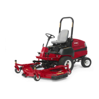
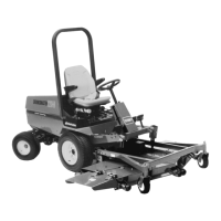
15
Setup
Note: Determine the left and right sides of the machine from the normal operating position.
Loose Parts
Note: Use the chart below to verify that all parts have been shipped.
Description
Qty. Use
Screw, M10 x 30 mm
Washer
4
4
Mounting steering cylinder to rear axle.
(Models 30627 & 30631 only)
Tie rod 1
Mount to steering arms.
(Models 30627 & 30631 only)
Bumper 1
Mount to axle support.
(Models 30627 & 30631 only)
Capscrew, 1/4 x 1/2 in.
Flange nut 1/4 in.
1
1
Secure steering hoses to bumper.
(Models 30627 & 30631 only)
Rear wheel 2 Mounting rear steering wheels (Metric nuts)
Front wheel 2 Mounting front wheels (English nuts)
Manual tube (shipped in tool box)
R-clamp
1
2
Holding the operator’s manual. Install on right
underside of seat.
Seat belt
Bolt, 7/16 x 1 in.
Lock washer, 7/16 in.
1
2
2
Installing the seat belts
Roll Bar (ROPS)
Bolt, 3/4 x 5-1/2 in.
Lock washer, 3/4 in.
Nut, 3/4 in.
1
4
4
4
Installing the roll bar
Right-hand ball joint (shipped in tool box) 1
Install ball joint (implement installation) and
connect lift cylinder
Hydraulic oil filter 1 Change after 10 hours
Parts catalog 1
Operator’s Manual (traction unit)
Models 30627/30626
2 Read before operating the machine.
Operator’s Manual (traction unit)
Models 30631/30630
1 Read before operating the machine.
Operator Training Material (Models 30626/30627
only)
1 Watch before operating the machine.
Certificate of Quality 1
Note: Some models may have already been set–up at factory.
 Loading...