42
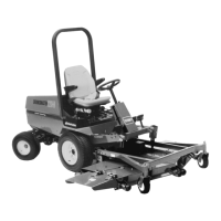
3. Remove boot from button end of PTO switch (Fig. 60).
Retain boot for reinstallation. Separate switch wire
connectors.
1
Figure 60
1. PTO switch
4. Remove front jam nut securing switch to mounting
bracket and remove switch.
5. Install new PTO switch to mounting bracket. Adjust
switch so it is depressed 1/2 in. (13 mm) when PTO
lever is moved to OFF position. Tighten jam nuts to
75 in.-lb. Install boot to switch.
Important Switch threads will be damaged if jam nuts
are over tightened.
6. Connect a continuity tester or ohm meter to switch
connector. With PTO lever in the ON position the
switch circuit should not have any continuity. If there
is continuity, recheck switch installation. If there is no
continuity, proceed to next step.
7. Move PTO lever to the OFF position. When PTO lever
is in its normal, released position, the PTO switch
should have continuity. If there is no continuity,
recheck switch installation. If there is no continuity,
proceed to next step.
8. Push switch connectors together.
9. Connect battery cable and install instrument cover.
Adjusting PTO Drive Belt
Tension
Important Check PTO belt tension initially after first
10 hours and 50 hours of operation and after every 100
hours of operation thereafter.
If belt begins to slip because it has stretched or because of
worn linkage adjust as follows:
1. Unlatch and remove instrument cover.
2. Move PTO control lever to ON position.
3. Measure length of PTO spring between flat–washers
(Fig. 61). There should be a spring length of 3-3/16 in.
(81 mm).
4. To adjust, hold head of adjusting screw with wrench
(under PTO actuating arm) and turn locknut (Fig. 61).
5. Move PTO lever to OFF position and install instrument
cover.
1
2
3
Figure 61
1. 3-3/16 in. (81 mm)
2. PTO actuating arm
3. Locknut
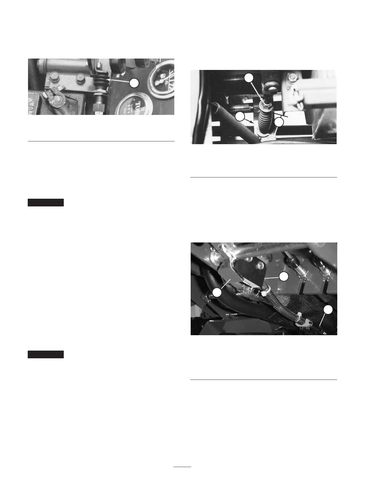
Adjusting the Parking Brake
Interlock Switch
1. Gap between parking brake shaft pivot paddle and
bottom of interlock switch (Fig. 62) should be
approximately 1/16” (Paddle must not contact switch).
1
2
3
Figure 62
1. Parking brake interlock
switch
2. Parking brake shaft pivot
paddle
3. Wire harness connector
2. To adjust gap, loosen switch mounting screws, adjust
gap and tighten screws.
3. Disconnect switch pigtail connector from wire harness.
4. Pull up on parking brake lever and depress brake pedal
to lock pedal into first click on latch.
 Loading...