15
5. Lower the hood and secure the latches.
FULL
1
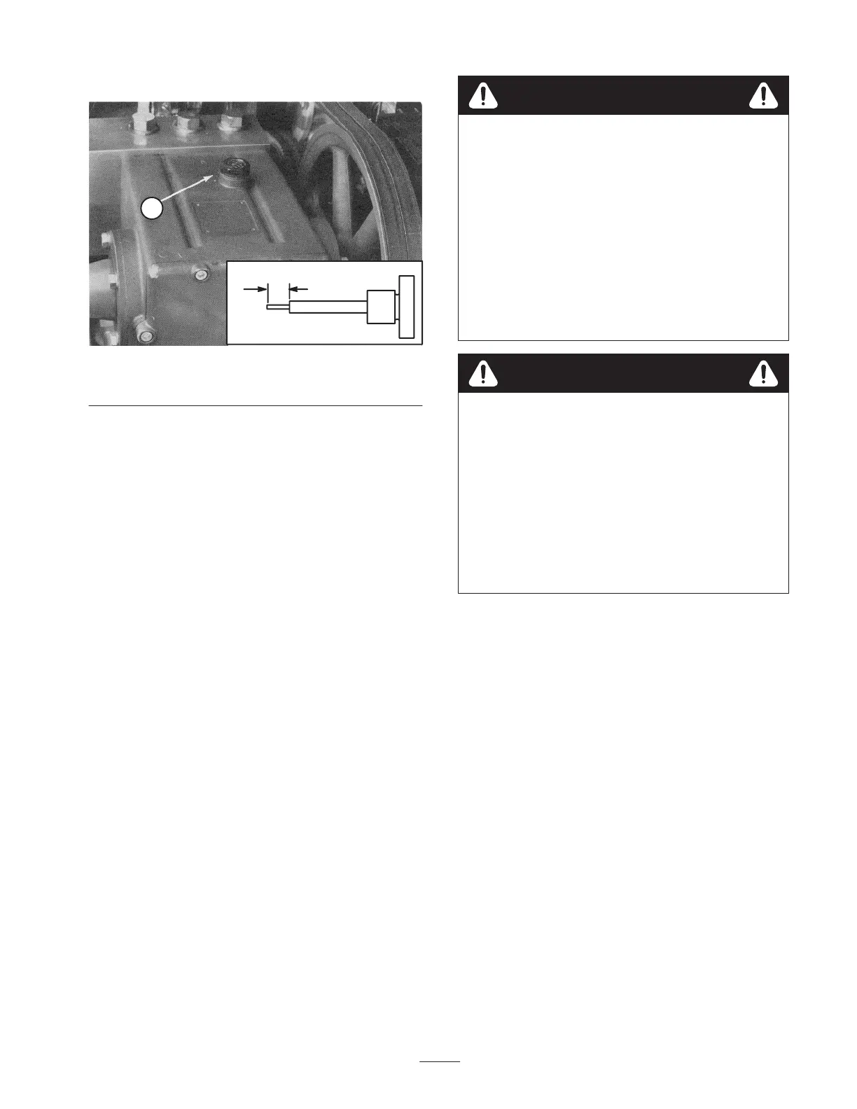
Figure 6
1. Dipstick/filler cap
Checking the Tire Pressure
The tires are over inflated for shipping. Make sure that the
front and rear tires are inflated to 8 to 12 p.s.i. (55 to
83 kPa).
Water System Accumulator
The Hydroject accumulator contains a high pressure
nitrogen gas pre–charge. The safety system on the aerator
will disable the water injection if the accumulator pressure
is too low or too high, and will illuminate one of the
accumulator pressure lights on the operators console.
Due to the operational requirements of the accumulator
design, the high pressure internal gas pre–charge can bleed
out during periods of inactivity. Storing the Hydroject for
extended periods of time (3 months or longer) and/or
seasonal temperature variances can affect the accumulators
ability to retain a sufficient pre–charge and seasonal
servicing (recharge) may be required.
If one of the accumulator charge indicator lamps
illuminates, contact your authorized Toro Distributor for
accumulator maintenance services.
Charge accumulators contain high pressure
nitrogen. Nitrogen is the only gas to use for
accumulator charging. Installing improper gases in
an accumulator can cause an explosion and death.
Charging requires special tools and precautions.
• Charge the accumulator in a well ventilated
area.
• Have the accumulator checked and charged by
an Authorized Toro Distributor.
• Wear eye protection.
• Keep your hands and face away from the gas
valve.
Warning
Failure to open the bleed valve before servicing
high pressure water components can cause
personal injury, dismemberment, or death.
Slowly open the high pressure water bleed valve
before servicing any component connected to the
high pressure water system. Opening the high
pressure bleed valve allows any trapped water to
escape from the system and also allows the
accumulator piston to move to the bottom of the
accumulator cylinder.
Warning
Note: Charged accumulators cannot be shipped via air
freight.
Operation
Note: Determine the left and right sides of the machine
from the normal operating position.
Controls
Ignition Switch
The ignition switch (Fig. 7), which is used to start and stop
the engine, has three positions: OFF, ON, and START.
 Loading...