19
Note: The injection operation starts approximately 4–5
seconds after the pump engages. Also, the injection system
will automatically stop if the traction bail is not engaged
within 3–4 seconds after starting the water system.
11. When aerating, work moving perpendicular from the
water supply to avoid running over the garden hose.
Use the front edge of the hood or rear corner of the
frame to align rows, if desired. When at the end of a
row, make an “S” maneuver and reverse the direction of
the aerator. Do not make sharp turns on a green or
scuffing from the tire may occur. Always maintain
awareness of what lies ahead in the direction of forward
travel.
12. Regulate the roller spray wash, if required, to remove
debris from the rollers.
Note: A small amount of water from the regulator bypass
may come out of the spray wash nozzles even with the
spray wash in the “OFF” position.
13. In areas where greater hole depth or more frequent
holes are desired, the engage button can be held down
to allow multiple shots while machine is stopped.
Important Hole depths can reach 20 inches or more
when making multiple shots, so be aware of what is buried
below the turf. Also, an excessive amount of holes and
muddy turf conditions may occur when making multiple
shots.
14. To stop water injection, press the red button. The
system continues for a few seconds after the button is
pressed. Raise the machine to the transport position,
disconnect the supply hose, and move to the next
location.
Checking the Interlock System
If safety interlock switches are disconnected or
damaged the machine could operate unexpectedly,
causing personal injury.
• Do not tamper with the interlock switches.
• Check the operation of the interlock switches
daily and replace any damaged switches before
operating the machine.
• Replace switches every two years regardless of
whether they are operating properly or not.
Caution
The purpose of the safety interlock system is to prevent the
engine from cranking or starting unless the traction bail is
in NEUTRAL and prevents the water system from
engaging if the machine is in the transport (raised) position.
It also stops aeration if the traction bail is released while
operating or if the machine is raised to the transport
position.
To do a functional check of interlock system:
1. Position the machine in a flat, open area on rough turf
and away from buried wires, plumbing, etc. Stop the
engine.
2. Move the traction bail up and down while trying to start
the engine. If the engine cranks, there is a malfunction
in the interlock system that must be corrected. If the
engine does not crank, proceed to step 3.
3. Connect the water supply to the machine. Turn on the
water supply and bleed all air out of the system. The
water pressure must be 30 psi or more. Start the engine.
Raise the machine to the transport position (up off the
rollers). Push the aerate ENGAGE button. If the water
pump engages and the machine begins aerating, there is
a malfunction in the interlock system that must be
corrected. If the machine does not begin aerating,
proceed to step 4.
4. Lower the machine to the aerate position (on the
rollers). Engage the traction bail to start the machine
moving. Push, then release the aerate ENGAGE button.
The water pump should engage immediately, then the
machine should begin aerating 5 seconds after the pump
engages. Release the traction bail to the neutral position
so that the machine stops moving. The water pump
should disengage 4 seconds after the traction bail
returns to neutral, then stop aerating after another 3
seconds. If the machine does not stop aerating when the
traction bail returns to neutral, there is a malfunction in
the interlock system that must be corrected. If the
machine stops aerating, proceed to step 5.
5. Engage the traction bail to start the machine moving,
then push the aerate ENGAGE button to begin aerating.
Push the aerate DISENGAGE button. The water pump
should disengage immediately, then stop aerating after 3
seconds. If the machine does not stop aerating, there is a
malfunction in the interlock system that must be
corrected.
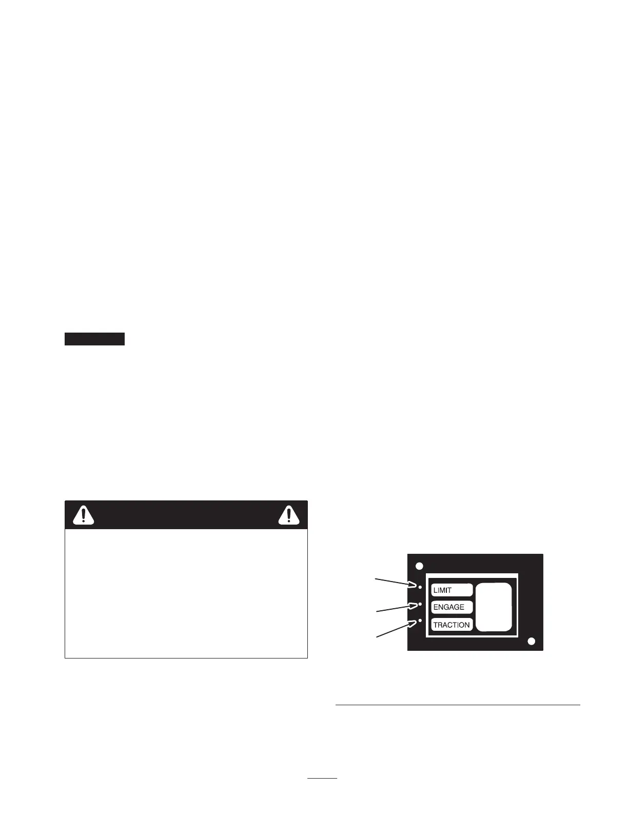
Note: Lights (LED’s) on the controller (Fig. 13) indicate
when the following inputs are made to the controller:
1
2
3
Figure 13
1. Red light
2. Green light
3. Yellow light
Red: Transport switch closed (traction bail in neutral)
 Loading...