4
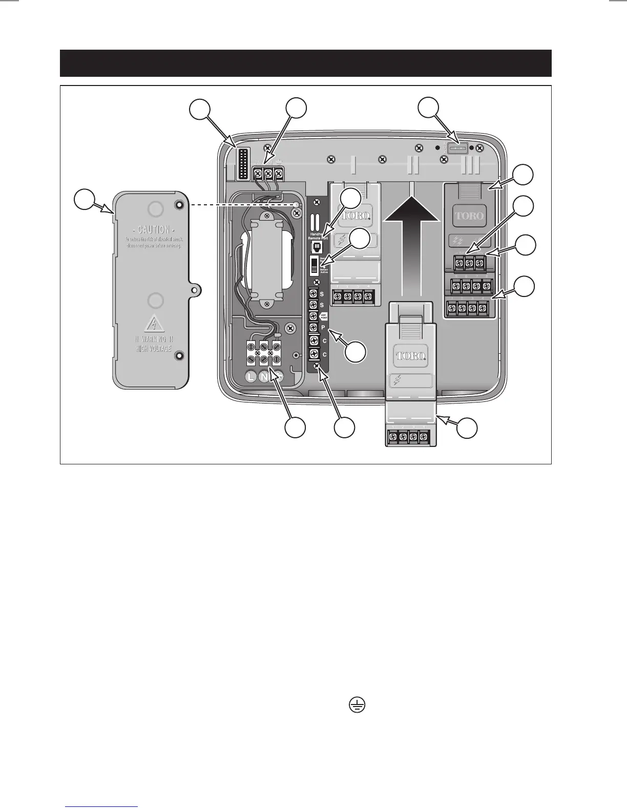
6 - Power supply compartment cover.
7 - Control module ribbon cable recep-
tacle.
8 - Transformer 24 VAC output connec-
tion terminals
9 - MR-1 remote connection port.
10 - Rain sensor bypass switch.
11 - Auxiliary port (not enabled).
12 - Flow sensor expansion module
(model TSM-8F indicated).
13 - Flow sensor wiring terminals
14 - Flow module master valve
wiring terminal.
15 - Expansion module valve
wiring terminals.
16 - Expansion module
(model TSM-4 shown).
17 - Wiring connection terminals:
S - Rain Sensor (2).
Hot Post (24 VAC source)
P - Pump Start/Master Valve
C - Valve (field) Common (2)
18 - Optional Earth Ground Lug
Attachment Screw.
19 - Input power wire connection
terminals:.
L - Line (mains 1)
N - Neutral (mains 2)
- Ground
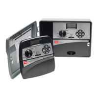
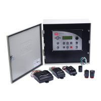
Internal Component Overview
6
19
18
16
17
15
14
13
12
11
8
7
10
9
 Loading...