 Loading...
Do you have a question about the Toshiba MMY-MUP1201HT8P-A and is the answer not in the manual?
| Brand | Toshiba |
|---|---|
| Model | MMY-MUP1201HT8P-A |
| Category | Air Conditioner |
| Language | English |
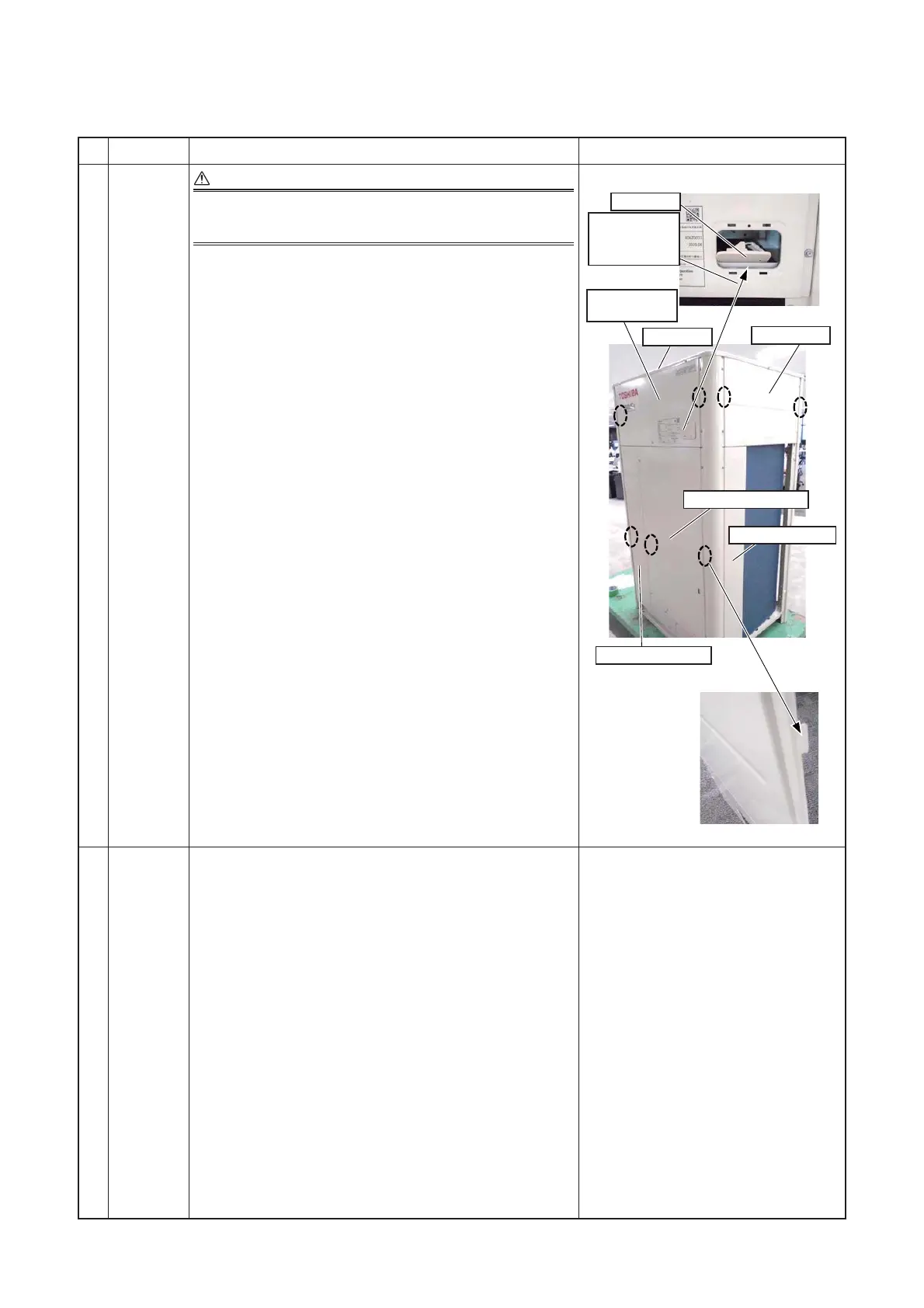
Provides critical safety warnings for handling electrical shock, high voltage, and general safety.
Covers warnings for all types of work, electrical work, working at heights, and handling units.
Highlights the high pressure of R410A and precautions to prevent accidents.
Provides detailed wiring diagrams for specific outdoor unit models.
Lists parts and their specifications for 50Hz outdoor units, indicating model compatibility.
Lists parts and their specifications for 60Hz outdoor units, indicating model compatibility.
Lists parts and their specifications for 50Hz outdoor units with "-A" suffix, indicating model compatibility.
Illustrates the refrigerant flow paths for various outdoor unit models in different operational states.
Shows refrigerant flow diagrams for header and follower units during cooling operation.
Illustrates refrigerant flow during single defrost operation for outdoor units.
Depicts refrigerant flow diagrams for header and follower units during heating operation.
Illustrates refrigerant flow during individual defrost operation for header and follower units.
Shows refrigerant flow for automatic emergency cooling operation under header and follower unit conditions.
Illustrates refrigerant flow for manual emergency cooling operation under header and follower unit conditions.
Depicts refrigerant flow for automatic emergency heating operation under header and follower unit conditions.
Shows refrigerant flow for manual emergency heating operation under header and follower unit conditions.
Illustrates refrigerant flow during the reclaim operation for outdoor units.
Explains the reverse defrosting method and conditions for initiating defrost operations.
Explains how to perform test operations on indoor units individually without external connections.
Provides step-by-step instructions for setting indoor unit function codes (DN codes) using wired remote controllers.
Details the procedure for setting outdoor unit function codes (O.DN) using interface board switches or wired remote controllers.
Explains how to enable the outdoor fan high static pressure function for duct installation.
Details the four patterns of priority operation mode settings for cooling and heating.
Explains the standard power peak-cut control settings using DIP switches and DN codes.
Details the extended power peak-cut control settings using DIP switches and DN codes.
Details the night operation function for reduced outdoor unit sound during quiet operation times.
Explains the notice code function for indicating caution or maintenance requirements.
Explains how to set the night operation time for reduced outdoor unit sound.
Outlines the step-by-step procedure for performing test operations on the system.
Lists essential checks for electric wiring and installation before initiating test operation.
Details checks to perform on outdoor and indoor units after main power is turned on.
Explains the procedure for setting addresses for indoor and outdoor units.
Details the steps for setting addresses and checking system information via the interface P.C. board.
Guides on setting DIP switches for header outdoor unit address and related configurations.
Provides step-by-step instructions for manually setting addresses using a wired remote controller.
Details the procedure for setting up TU2C-Link or TCC-Link communication between units.
Provides troubleshooting steps for issues encountered during test operation, including check codes.
Explains how to perform cooling and heating test operations using remote controllers and the outdoor unit interface.
Provides an overview of applicable models, tools, and general troubleshooting behaviors.
Explains how to analyze check codes detected by various devices to identify problems.
Guides on troubleshooting based on check codes and history displayed on the remote controller.
Correlates check codes displayed on remote controllers and outdoor units with specific locations and causes.
Provides detailed diagnostic flowcharts for various check codes to identify and resolve issues.
Explains the procedure for setting compressor backup operation when one compressor fails.
Details how to set up backup operation for outdoor units when a unit fails.
Provides the step-by-step procedure for setting backup operation for a failed follower outdoor unit.
Outlines the procedure for setting backup operation for a failed header outdoor unit.
Details the method for recovering refrigerant from a troubled outdoor unit for repair.
Outlines the procedure for refrigerant recovery when the troubled outdoor unit can be powered on.
Details the refrigerant recovery procedure when the troubled outdoor unit cannot be powered on.
Outlines the general procedure for replacing compressors, including safety warnings.
Details how to check compressor oil color and adjust oil amounts for new compressors.