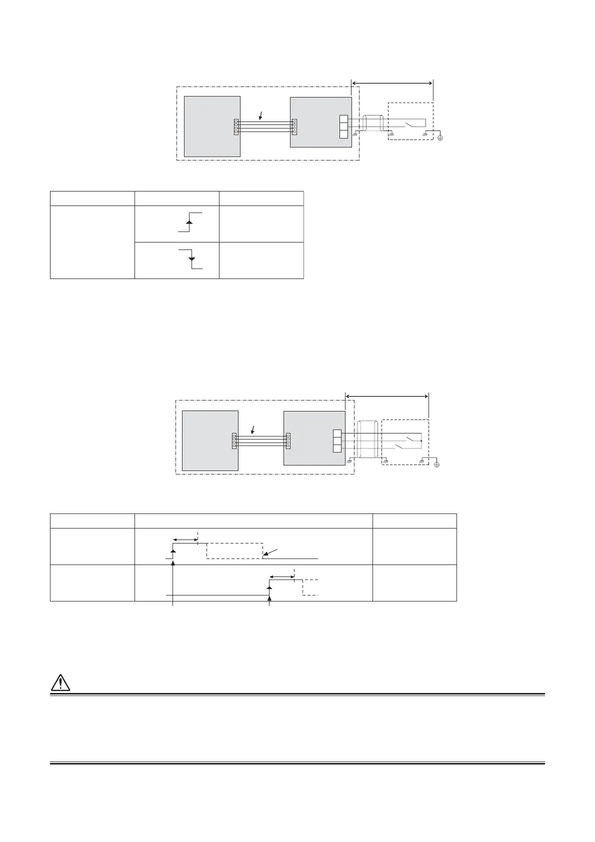
6-6-3-3. Snowfall Fan Control
Operation
An external snowfall signal turns on the outdoor unit fan.
Operation
The system is started/stopped from the outdoor unit.
• Input signal is detected in the rising edge between OFF and ON of SW1/SW2 and the control is accepted in
100 msec from the edge.
• When COOL terminals (SW1 and SW2) are simultaneously turned ON, the control turned ON first is valid,
and the control turned ON later is invalid.
CAUTION
(1) Do not turn on the COOL (SW1) and HEAT (SW2) terminals simultaneously.
(2) COM terminals have DC12 V output with a basic insulation. Use a switch, such as a relay or photocoupler,
insulated from a controller (locally procured) for CO (Change-Over) contact or NO (normally-open) contact.
DC12 V has a current-limiting resistor of 3.3 :.
For non-voltage contacts, use a relay with minimum applicable load of DC12V,3mA or less.
The optional P.C. board should be connected to the header outdoor unit (U1).
SW1: Snowfall detection switch (snowfall sensor)
PJ17CN509
TB1
SW1
COM
HEAT
COOL
Locally procured
Optional PCB
Snowfall sensor
Header outdoor unit
Connection
cable
Outdoor unit
interface PCB
Shield
wire
Terminal Input signal Operation
COOL
(SW1)
All indoor units
operate together
All indoor units
operate together
ON
OFF
ON
OFF
SW1: Operation input switch
SW2: Stop input switch
PJ17CN512
TB1
SW1
SW2
COM
HEAT
COOL
Locally procured
Optional PCB
Header outdoor unit
Outdoor unit
interface PCB
Connection
cable
Shield
wire
Terminal Input signal Operation
COOL
(SW1)
Turns on all indoor
units
HEAT
(SW2)
Turns off all indoor
units
ON
OFF
Batch-
operation
accepted
Batch-operation Batch-stop
Batch-
stop
accepted
100ms
It does not matter whether the state is ON or
OFF after 100 msec from the signal input.
Turn SW1 OFF before sending
ON
OFF
100ms
The input signal is recognized during it
s rising/falling phase.
(After reaching the top/bottom of the r
ising/f
alling edge
, the signal must remain there for at least 100 ms.)
The optional P.C. board should be connected to the header outdoor unit (U1).
COM terminals have DC12 V output with a basic insulation. Use a switch, such as a relay or photocoupler,
insulated from a controller (locally procured) for CO (Change-Over) contact or NO (normally-open) contact.
DC12 V has a current-limiting resistor of 3.3 :.
For non-voltage contacts, use a relay with minimum applicable load of DC12V,3mA or less.
6-6-3-4. External master ON/OFF Control
 Loading...