Optional P.C.board Outdoor unit interface P.C.board
* The upper limit X% can be regulated with the outdoor DN Code (O.DN) [00E].
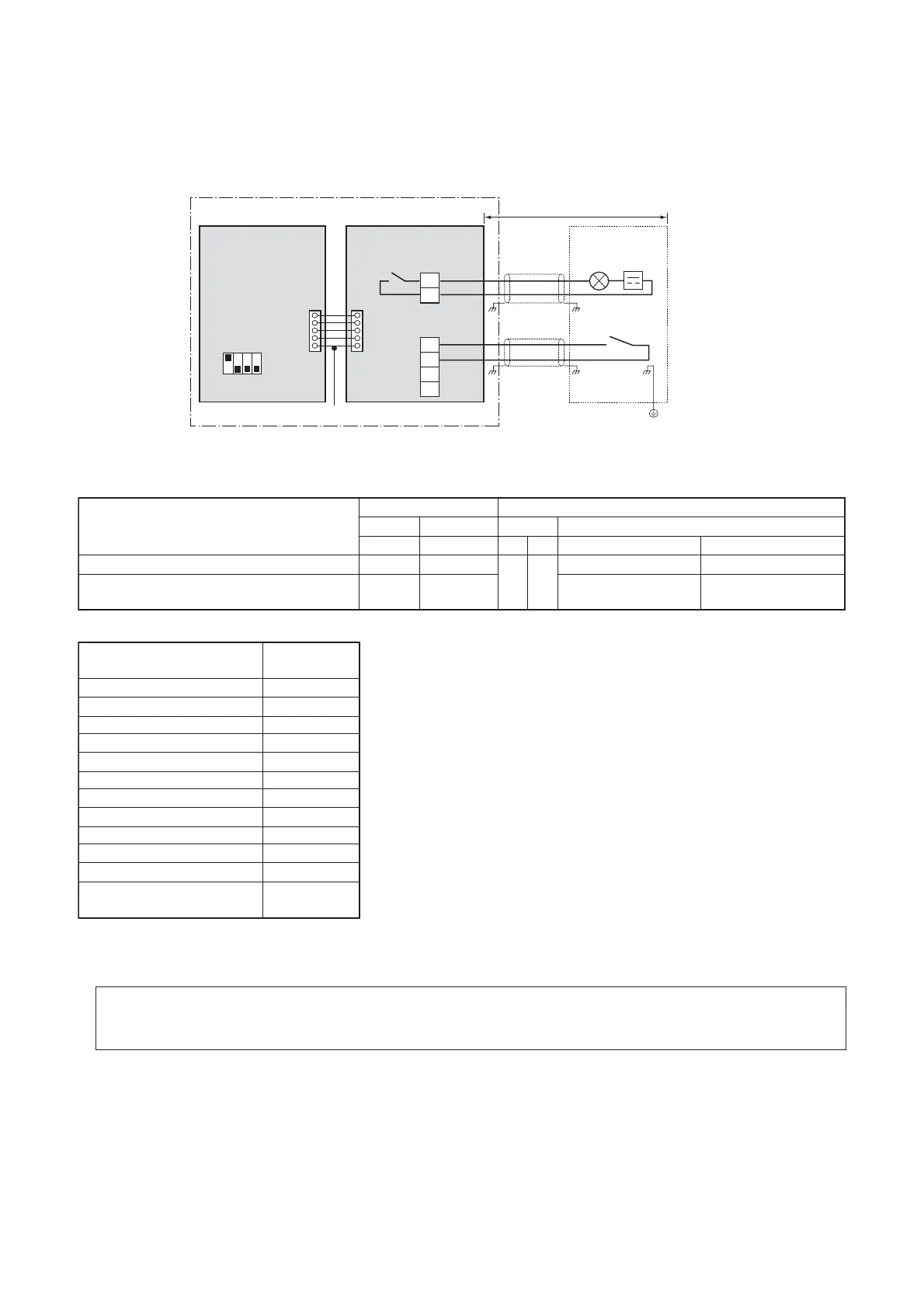
Demand: power peak-cut control
[2-stage switching] < SW105 bit1 ON, bit2 OFF >
Power peak-cut control turns ON when SW 1 in the wiring example is ON (continuous make).
Display relay SW105 Outdoor unit DN Code [00E]
SW1
InputControl item
(L1) Bit1 Bit2
Factory default [00E] = 15
[00E] = 0 to 10
Input demand OFF signal to release the demand
Outdoor unit DN Code (O.DN)
[00E]
X
0
1
2
3
4
5
6
7
8
9
10
100%
95%
90%
85%
80%
75%
70%
65%
60%
55%
50%
15 (factory default)
0%
(forced stop)
OFF OFF
ON OFF
100% (normal operation) 100% (normal operation)
Input demand ON signal to control the demand ON ON 0% (forced stop)
Approx. X (50% to 100%)
(upper limit regulated)
Note 1: Specifications of display relay contact
• The terminal for display output ([Operation] terminal) must satisfy the following electrical rating.
<Electrical Rating>
220 to 240 VAC, 10 mA or more, 1 A or less
24 VAC, 10 mA or more, 1 A or less (non-conductive load)
When connecting a conductive load (e.g. relay coil) to the display relay load, insert a surge killer CR (for an
AC power supply) or a diode for preventing back electromotive force (for a DC power supply) on the bypass
circuit.
PJ17
TB1
TB2
COM
ON
COM
OFF
CN513
SW105
Bit1 ON, Bit2 OFF
L1
SW1
ON
OFF
1234
[ON]
[OFF]
Connection cable
Locally procured
[OPERATION]
L1: Display lamp ensuring power peak cut control
Optional PCB
Header outdoor unit
Shield wire
Shield wire
Outdoor unit
interface PCB
Display
relay
Power
supply
Note 2: COM contact specifications
• COM terminals have DC12 V output with a basic insulation. Use a switch, such as a relay or photocoupler,
insulated from a controller (locally procured) for CO (Change-Over) contact or NO (normally-open) contact.
• DC12 V has a current-limiting resistor of 3.3 :.
• For non-voltage contacts, use a relay with minimum applicable load of DC12V,3mA or less.
(2) Two-core cable support
Setting SW105 bit1 on I/F P.C.board of the header outdoor unit to ON allows ON/OFF power peak-cut control
to be switched using [ON] terminal input (SW1) alone.
 Loading...