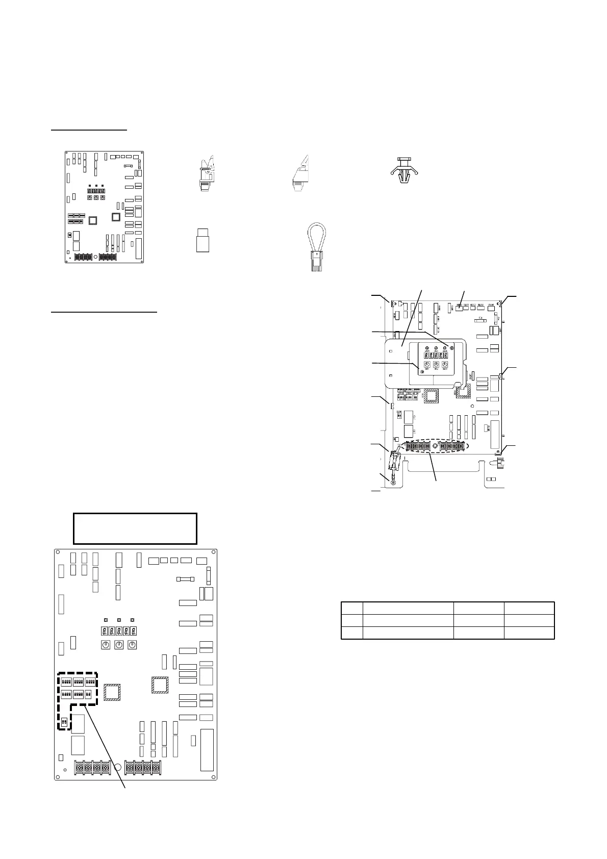
13-1-3. Interface P.C. Board (MCC-1747) Replacement Procedure
Subject part 43T6W890: ALL model
This Interface service P.C. board is commonly installed in different models. Please perform the change by
a model after replacement of a service board.
Included item:
MCC-1747 : 1pcs
Spacer : 4pcs
Spacer : 2pcs
Support : 1pcs
Bush : 3pcs
Short Connector : 1pcs
%0%0%0%0%0
%0
10
10
10
10
10
10
+%
+%
59 59 59
2
10
0%0%0%
(
(
%0
%0
%0 %0
%0 %0
%0%0 %0
%0%0
59
59
59
59
59
59
59
%0
..
%0
%0
%0
%0
59 59 59
%0
%0
7 7 7 7
7X 7J7X 7J 7E 7E
5*+'.&5*+'.&
5*+'.&
7 7
5*+'.&
CN306 Red
Space
Resin Cover
Space
Spacer
Spacer
Space
Spacer
Scre
Scre
Scre
Screw terminal
%0%0%0%0%0
%0
10
10
10
10
10
10
+%
+%
59 59 59
2
10
0%0%0%
(
(
%0
%0
%0 %0
%0 %0
%0%0 %0
%0%0
59
59
59
59
59
59
59
%0
..
%0
%0
%0
%0
59 59 59
%0
%0
7 7 7 7
7X 7J7X 7J 7E 7E
5*+'.&5*+'.&
5*+'.&
7 7
5*+'.&
Interface P. C. Board
㧔43T6W890㧕
DIP Switch
The torque of the screws
Screw terminals
M410 1.2N• m
Screw
M325 0.6N• m
Screw
M48 1.2N• m
Replacement steps:
(1) Turn off the power supply of the outdoor unit and wait at
least 5 minutes for the capacitor to discharge.
(2) Remove all of the connectors and wiring for a screw
terminal (
i
) which were connected to the interface P.C.
board. (Remove the connectors by pulling the connector
body. Do not pull the wire.)
(3) Remove three screws (
j
:2pcs,
k
:1pcs).
(These screws are to be re-used after procedure.)
(4) Remove the P.C. board from the four spacers
(
d
:4pcs,
e
:2pcs)
(5) Set the DIP switch settings of the service board to match
the switch settings of the P.C. board being replaced.
(6) Using a new spacer (
d
,
e
), a support (
f
), and a bush (
g
),
attach the service board.
(7) Re-connect the connectors and resin cover, screws (
j
,
k
), screw
terminals (
i
). Be sure that all the connectors and the screw
terminals are connected correctly and securely inserted.
(8) The product with HP-SW2 should connect HP-SW2 to CN306.
The product without HP-SW2 should connect a short connector to
CN306.
Caution: Please do not use a short connector for a product with
HP-SW2.
The protection circuit does not operate.
(9) If a component on the P.C. board is bent during board replacement,
adjust it manually ensuring that it is not short-circuited or contact
other parts.
(10) Install the cover, then turn on the power supply.
 Loading...