6-6-3-6. Operation Mode Selection Control
NOTE
SW1: COOL mode selection switch
SW2: HEAT mode selection switch
Indoor unit operation intervention function
The statuses of indoor units operating in a mode other the selected operation mode can be switched by setting
the outdoor DN Code of the header outdoor unit.
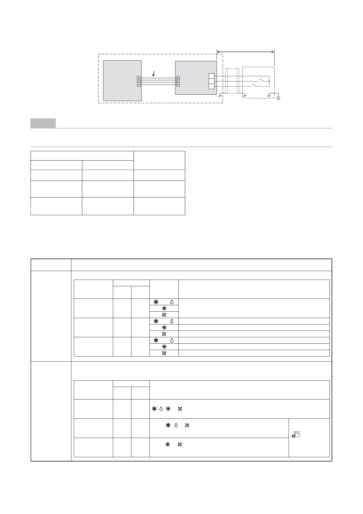
The optional P.C. board should be connected to the header outdoor unit (U1).
SW1: Cooling mode specified input switch
SW2: Heating mode specified input switch
PJ17CN510
TB1
SW1
SW2
COM
HEAT
COOL
Locally procured
Optional PCB
Header outdoor unit
Shield
wire
Connection
cable
Outdoor unit
interface PCB
, , or can be selected.
• Only , or can be selected.
• Indoor units in Heat mode are forcibly switched to the Cool mode.
Outdoor DN Code
(O.DN)
Details of Processing
O.DN [008] = 0
(factory default)
Unallowed indoor units in a mode other than the P.C.board selection modes are not treated as priority (thermostat OFF state).
P.C. board
selection mode
Input Signal
Remote
control
COOL
SW1
HEAT
SW2
Normal OFF OFF
or
Follow the remote controller.
Cooling operation
only allowed
ON OFF
or Follow the remote controller (Normal cooling operation).
Thermostat OFF (Air blow operation at super-slow blow rate)
Follow the remote controller (Normal air blow operation).
Heating operation
only allowed
OFF ON
or Thermostat OFF (Air blow operation at blow rate set on remote control)
Follow the remote controller (Normal heating operation).
Follow the remote controller (Normal air blow operation).
Operation State
O.DN [008]= 1
Only operation modes and air blow operation selected on the P.C.board can be selected on the remote controller.
When the input signal is turned ON, indoor units operated in a mode other than the P.C.board selection mode are forcibly
switched to the P.C.board selection modes.
P.C. board
selection mode
Input Signal
COOL
SW1
HEAT
SW2
Normal OFF OFF
COOL ON OFF
HEAT OFF ON
• Only or can be selected.
•
Indoor units in Cool or Dry mode are forcibly switched to the Heat mode.
When using the
remote control,
(mode select
control) indicator
is displayed.
Remote control
• COM terminals have DC12 V output with a basic insulation. Use a switch, such as a relay or photocoupler,
insulated from a controller (locally procured) for CO (Change-Over) contact or NO (normally-open) contact.
• DC12 V has a current-limiting resistor of 3.3 :.
• For non-voltage contacts, use a relay with minimum applicable load of DC12V,3mA or less.
Input signal
Operation
COOL (SW1) HEAT (SW2)
OFF OFF Normal operation
ON OFF
Only cooling
operation allowed
OFF ON
Only heating
operation allowed
 Loading...