TERMINOLOGY
2.
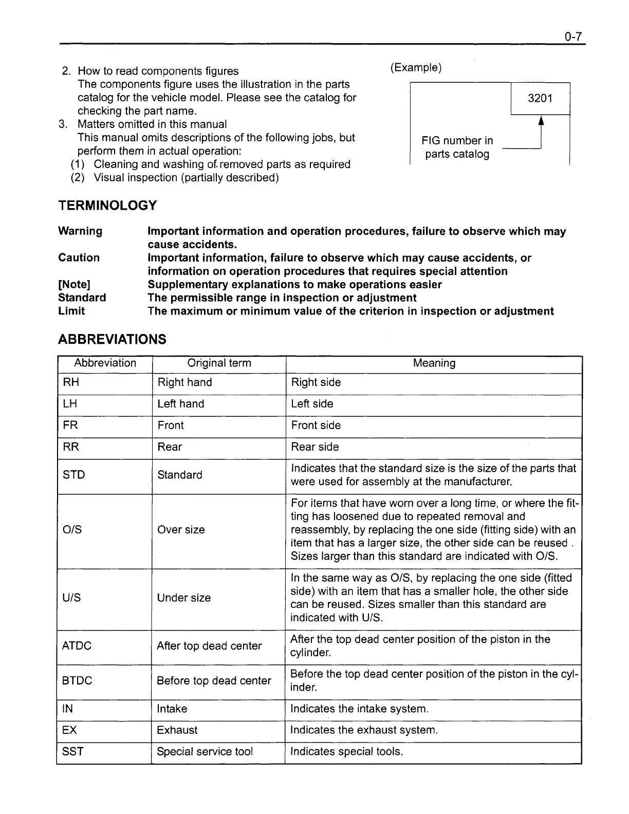
How to read components figures
(Example)
Warning
Important information and operation procedures, failure to observe which may
cause accidents.
Caution
Important information, failure to observe which may cause accidents, or
information on operation procedures that requires special attention
[Note] Supplementary explanations to make operations easier
Standard The permissible range in inspection or adjustment
Limit The maximum or minimum value of the criterion in inspection or adjustment
The components figure uses the illustration in the parts
catalog for the vehicle model. Please see the catalog for
checking the part name.
3.
Matters omitted in this manual
This manual omits descriptions of the following jobs, but
perform them in actual operation:
ABBREVIATIONS
320
1
FIG number in
parts catalog
(1) Cleaning and washing of. removed parts as required
(2)
Visual inspection (partially described)
I
FR
1
Front
1
Front side
I
Abbreviation
RH
LH
I
RR
1
Rear
1
Rear side
I
1
STD
/
Standard
Original term
Right hand
Left hand
lndicates that the standard size is the size of the parts that
were used for assembly at the manufacturer.
Meaning
Right side
Left side
1
Over size
Under size
For items that have worn over a long time, or where the fit-
ting has loosened due to repeated removal and
reassembly, by replacing the one side (fitting side) with an
item that has a larger size, the other side can be reused
.
Sizes larger than this standard are indicated with 01s.
In the same way as OIS, by replacing the one side (fitted
side) with an item that has a smaller hole, the other side
can be reused. Sizes smaller than this standard are
indicated with
UIS.
I
ATDC
I
BTDC
Afier top dead center
After the top dead center position of the piston in the
cylinder.
I
IN
(
Intake
I
Indicates the intake system.
I
Before top dead center
Before the top dead center position of the piston in the cyl-
inder.
EX
SST
Exhaust
Special service tool
Indicates the exhaust system.
Indicates special tools.
 Loading...