Controls Interface
RTAC-SVX01J-EN 11 5
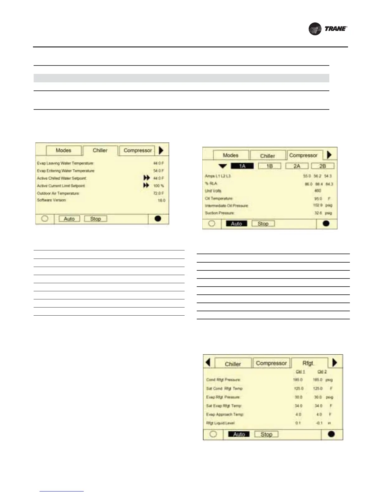
Chiller Screen
The chiller screen is a summary of the chiller activity.
Compressor Screen
The compressor screen displays information for the one,
two, three, or four compressors in the format shown.The
top line of radio buttons allows you to select the
compressor of interest.The next three lines show the
compressor operating mode.The compressor radio
buttons and the compressor operating mode lines don’t
change as you scroll down in the menu.
The top screen has no upward scroll keys.The single arrow
down
scrolls the screen one line at a time. As soon as the
display is one line away from the top, the upward pointing
arrow appears.
The last screen has a single arrow to scroll upward one line
at
a time.When in the last position, the single down arrow
disappears.
Each compressor has its own screen depending on which
radio
key is pressed. When toggling between compressor
screens, say to compare starts and run time, the same lines
can be seen without additional key strokes. For example,
toggling from the bottom of the compressor 1A menu
accesses the top of the compressor 2A menu.
.
Refrigerant Screen
The refrigerant screen displays those aspects of the chiller
related to the refrigerant circuits.
Service Tool Lockout
The compressor is in the process of shutdown due to a command from the TechView
Service T
ool to be "locked out" and inoperative. This setting is nonvolatile and operation
can only be restored by using TechView to "unlock" it.
Table 56. Compressor modes (continued)
Compressor Modes Description
Top Level Mode
Sub-modes
Table 57. Chiller screen
Description Resolution Units
Evap Leaving Water Temperature X.X F / C
Evap Entering Water Temperature X.X F / C
Active Chilled Water Setpoint X.X F / C
Active Current Limit Setpoint X % RLA
Out Door Temperature X.X F / C
Software Type RTA Text
Software Version X.XX Text
Table 58. Compressor screen
Description Resolution Units
Amps L1 L2 L3 XXX Amps
% RLA L1 L2 L3 X.X % RLA
Unit Volts XXX Volts
Oil Temperature X.X F / C
Intermediate Oil Pressure X.X Pressure
Suction Pressure X.X Pressure
Starts/ Run Hours X, XX:XX hr:min
 Loading...


