RTAC-SVX01J-EN 41
Installation - Mechanical
Location Requirements
Noise Considerations
Locate outdoor unit away from sound sensitive areas. If
required, install rubber vibration isolators in all water
piping and use flexible electrical conduit. Consult an
acoustical engineer for critical applications. Also refer to
Trane Engineering Bulletins for application information on
RTAC chillers.
Foundation
A base or foundation is not required if unit location is level
and strong enough to support unit’s operating weight as
listed in “General Data,” p. 11, Table 1, p. 12 through
Table 10, p. 21. Provide rigid, non-warping mounting pads
or concrete foundation of sufficient strength and mass to
support unit operating weight (including piping, and full
operating charges of refrigerant, oil and water). Once in
place, outdoor unit must be level within 1/ 4" (6 mm) over
its length and width.
Trane Company is not responsible for equipment
problems resulting from an improperly designed or
constructed foundation.
Note: To allow for cleaning under the condensing coil, it
is recommended that an opening be left between
the unit base and the concrete pad.
Clearances
Provide enough space around the outdoor unit to allow the
installation and maintenance personnel unrestricted
access to all service points. Refer to submittal drawings for
the unit dimensions. A minimum of 4 feet (1.2 m) is
recommended for compressor service. Provide sufficient
clearance for the opening of control panel doors. Refer to
Figure 5, p. 23 through Figure 9, p. 25 in “Dimensions and
Weights,” p. 23 for minimum clearances. In all cases, local
codes which require additional clearances will take
precedence over these recommendations.
Rigging
Lifting Procedure
Important: Do not fork lift unit.
See Table 12, p. 38 through Table 18, p. 40 for lifting
weights and Table 19, p. 43 and Table 20, p. 43 for center of
gravity (CG) dimensions.
WARNING
Heavy Objects!
Ensure that all the lifting equipment used is properly
rated for the weight of the unit being lifted. Each of the
cables (chains or slings), hooks, and shackles used to
lift the unit must be capable of supporting the entire
weight of the unit. Lifting cables (chains or slings) may
not be of the same length. Adjust as necessary for even
unit lift. Other lifting arrangements could cause
equipment or property damage. Failure to follow
instructions above or properly lift unit could result in
unit dropping and possibly crushing operator/
technician which could result in death or serious injury.
WARNING
Improper Unit Lift!
Test lift unit approximately 24 inches to verify proper
center of gravity lift point. To avoid dropping of unit,
reposition lifting point if unit is not level. Failure to
properly lift unit could result in unit dropping and
possibly crushing operator/technician which could
result in death or serious injury and possible
equipment or property-only damage.
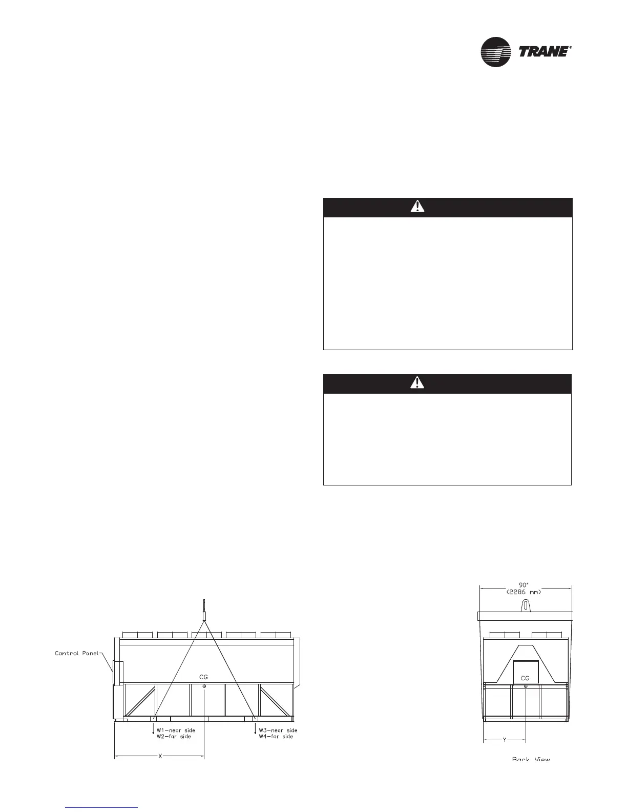
Figure 13. Lifting the unit (packaged and remote) 15-21 foot base
 Loading...


