Installation - Electrical
90 RTAC-SVX01J-EN
set via the DynaView or through digital communication
withTracer (Comm3).The arbitration of the various chilled
water setpoint sources is described in the flow charts at the
end of the section.
The chilled water setpoint may be changed from a remote
location
by sending either a 2-10VDC or 4-20 mA signal to
the 1U6, terminals 5 and 6 LLID. 2-10 VDC and 4-20 mA
each correspond to a 10 to 65°F (-12 to 18°C) external
chilled water setpoint.
The following equations apply:
If the ECWS input develops an open or short, the LLID will
repor
t either a very high or very low value back to the main
processor.This will generate an informational diagnostic
and the unit will default to using the Front Panel
(DynaView) Chilled Water Setpoint.
TechView ServiceTool is used to set the input signal type
from
the factory default of 2-10 VDC to that of 4-20 mA.
TechView is also used to install or remove the External
ChilledWater Setpoint option as well as a means to enable
and disable ECWS.
External Current Limit Setpoint (ECLS)
Option
Similar to the above, the CH530 also provides for an
optional External Current Limit Setpoint that will accept
either a 2-10VDC (default) or a 4-20 mA signal.The Current
Limit Setting can also be set via the DynaView or through
digital communication withTracer (Comm 3). The
arbitration of the various sources of current limit is
described in the flow charts at the end of this section.The
External Current Limit Setpoint may be changed from a
remote location by hooking up the analog input signal to
the 1 U6 LLID terminals 2 and 3. Refer to the following
paragraph on Analog Input Signal Wiring Details.The
following equations apply for ECLS:
If the ECLS input develops an open or short, the LLID will
repor
t either a very high or very low value back to the man
processor.This will generate an informational diagnostic
and the unit will default to using the Front Panel
(DynaView) Current Limit Setpoint.
TheTechView ServiceTool must be used to set the input
signal
type from the factory default of 2-10 VDC to that of
4-20 mA current.TechView must be also be used to install
or remove the External Current Limit Setpoint Option for
field installation, or can be used to enable or disable the
feature (if installed).
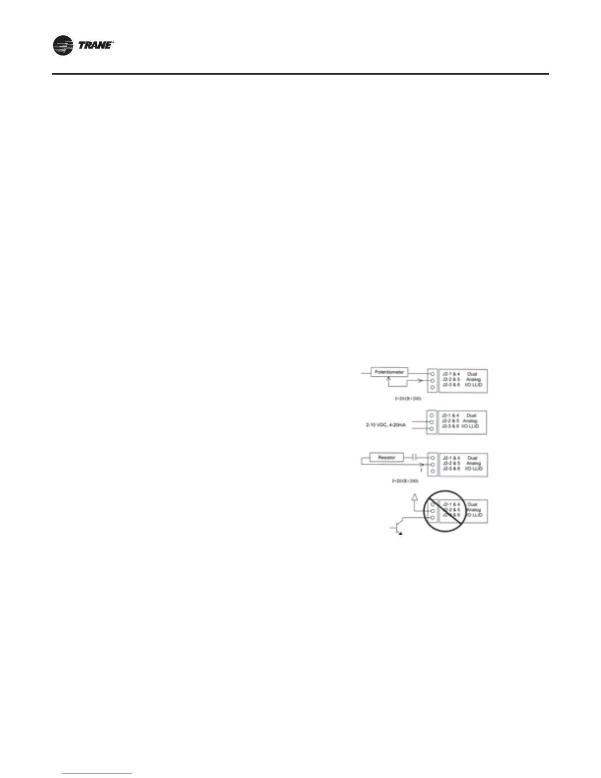
ECLS and ECWS Analog Input Signal Wiring
Details:
Both the ECWS and ECLS can be connected and setup as
either a 2-10 VDC (factory default), 4-20 mA, or resistance
input (also a form of 4-2OmA) as indicated below.
Depending on the type to be used, theTechView Service
Tool must be used to configure the LLID and the MP for the
proper input type that is being used.This is accomplished
by a setting change on the Custom Tab of the
Configuration View withinTechView.
Important: F
or proper unit operation, BOTH the ECLS
and ECWS settings MUST be the same (2-10
VDC or 4-20mA), even if only one input is to
be used.
The J2-3 and J2-6 terminal is chassis grounded and
terminal
J2- 1 and J2-4 can be used to source 12 VDC.The
ECLS uses terminals J2-2 and J2-3. ECWS uses terminals
J2-5 and J2-6. Both inputs are only compatible with
high-side current sources.
Chilled Water Reset (CWR)
CH530 resets the chilled water temperature set point
based on either return water temperature, or outdoor air
temperature. Return Reset is standard, Outdoor Reset is
optional.
The following shall be selectable:
• One of three ResetTypes: None, Return Water
Temperature Reset, Outdoor AirTemperature Reset, or
Constant Return WaterTemperature Reset.
• Reset Ratio Set Points.
For outdoor air temperature reset there shall be both
positi
ve and negative reset ratio's.
• Start Reset Set Points.
Voltage Signal Current Signal
As generated from
external source
VDC=0.1455*(ECWS)+
0.5454
mA=0.2909(ECWS)+
1.0909
As processed by
CH530
ECWS=6.875*(VDC)-
3.75
ECWS=3.4375(mA)-
3.75
Voltage Signal Current Signal
As generated from
external source
VDC+0.133*(%)-6.0 mA=0.266*(%)-12.0
As processed by
UCM
%=7.5*(VDC)+45.0 %=3.75*(mA)+45.0
Figure 30. Wiring examples for ECLS and ECWS
 Loading...


