Installation - Mechanical — Remote Evaporator Option
60 RTAC-SVX01J-EN
Example Liquid Line Sizing
For this example, refer to Table 29, p. 58, Table 30, p. 59
and Figure 25, p. 60. Assume a 70 ton circuit and a leaving
water temperature of 49 degrees F.
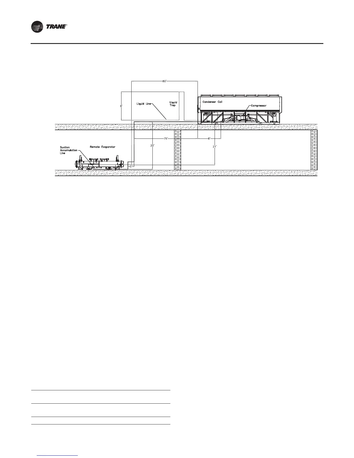
1. From Figure 25, p. 60, the actual length of field
installed piping is:
80+8+8+21=117feet
2. Estimate equivalent line length:
117 feet x 1.5 = 175 feet
3. From Table 29, p. 58 for a 70 ton circuit, for 175
equivalent feet the OD is 1.375 inches.
Note: Use the 0 ft. column since the condenser is above
the evap
4. In Figure 25, p. 60, there are six long-radius elbows.
From Table 30, p. 59, for 1.375 inch elbows, the
equivalent feet is:
6 elbows x 2.2 feet = 13.2 feet
5. Adding equivalent feet from step #4 to step #1 gives:
13.2 feet + 117 feet = 130.2 feet
6. From Table 29, p. 58, for a 70 ton circuit, for 125
equivalent feet (nearest to 130.2), the O.D. is 1- 3/8
inches.
Liquid Line size = 1-3/8 inches
Suction Line Sizing Steps
The steps to compute suction line size are as follows:
1. Break the suction line into it's Vertical/Upflow and
Horizontal/Downflow components.
2. From Table 32, p. 60, select the appropriate Vertical/
Upflow suction line outside diameter according to the
circuit tonnage.This is the diameter of the upflow
suction line and any fittings in the upflow line.
3. From Table 32, select the appropriate Horizontal/
Downflow suction line outside diameter according to
the circuit tonnage.This is the diameter of the upflow
suction line and any fittings in the upflow line.
Note: The diameters of the upflow, and horizontal or
downflow portions of the suction line may differ
depending on the application.
Example Suction Line Sizing
For this example, refer to Table 32 and Figure 25, p. 60
assume a 70 ton circuit and a leaving water temperature of
49 degrees F.
1. From Table 32 the vertical/upflow suction line is: 3 5/8”
O.D.
2. From Table 32, the horizontal/downflow line is: 3 5/8”
O.D.
Note: In this example, the horizontal line is pitched
downward in the direction of flow.
Suction Accumulator Sizing
Use Figure 31, p. 59 to calculate length and size of the
required suction accumulator(s).
Example of Suction Accumulator Line Sizing
Use Figure 25, p. 60 and the same assumptions from the
liquid line sizing example to calculate the suction
accumulator line size and length.
In this case the accumulator is installed at the evaporator.
Figure 25. Liquid line sizing example
Table 32. Suction line sizes
Vertical/Upflow and Horizontal/Downflow Suction Lines
O.D. (Type L Copper)
LWT (F)
70 ton
circuit
85ton
circuit
100 ton
circuit
120 ton
circuit
40 - 60 3 5/8” 3 5/8” 4 1/8” 4 1/8”
 Loading...


